System and method for power generation in Rankine cycle

a technology of power generation system and rankine cycle, which is applied in the direction of steam engine plants, machines/engines, mechanical equipment, etc., can solve the problems of shifting the operating temperature of the plant away from the design point, and losing efficiency

Inactive Publication Date: 2009-09-29
AI ALPINE US BIDCO INC
View PDF9 Cites 27 Cited by
  • Summary
  • Abstract
  • Description
  • Claims
  • Application Information

AI Technical Summary

Problems solved by technology

Geothermal plants, for example, may be designed for a particular temperature of geothermal heating fluid from the earth, but lose efficiency as the ground fluid cools over time, thereby shifting the plant operating temperature away from its design point.

Method used


Image

  • System and method for power generation in Rankine cycle
  • System and method for power generation in Rankine cycle
  • System and method for power generation in Rankine cycle

Examples


Embodiment Construction

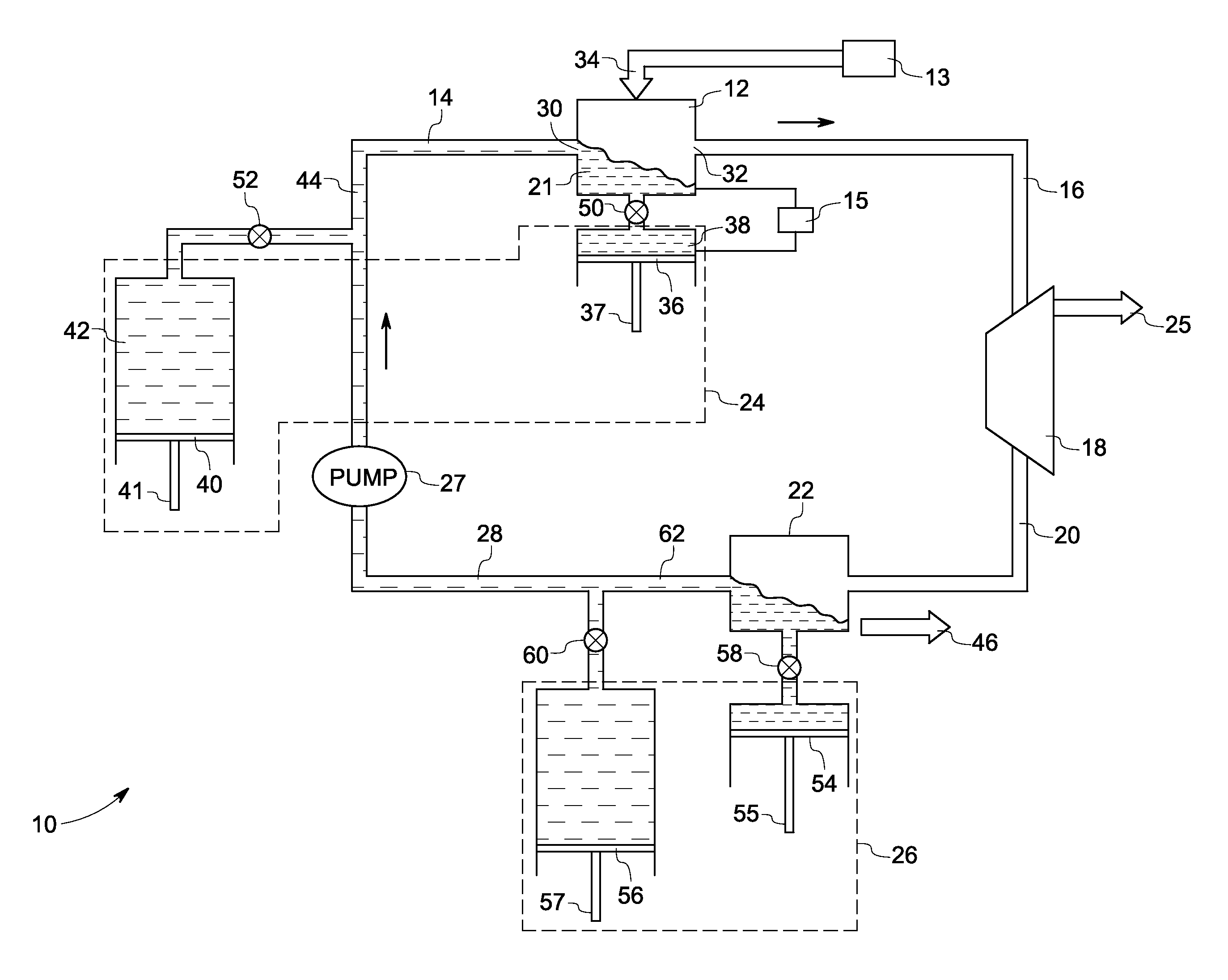
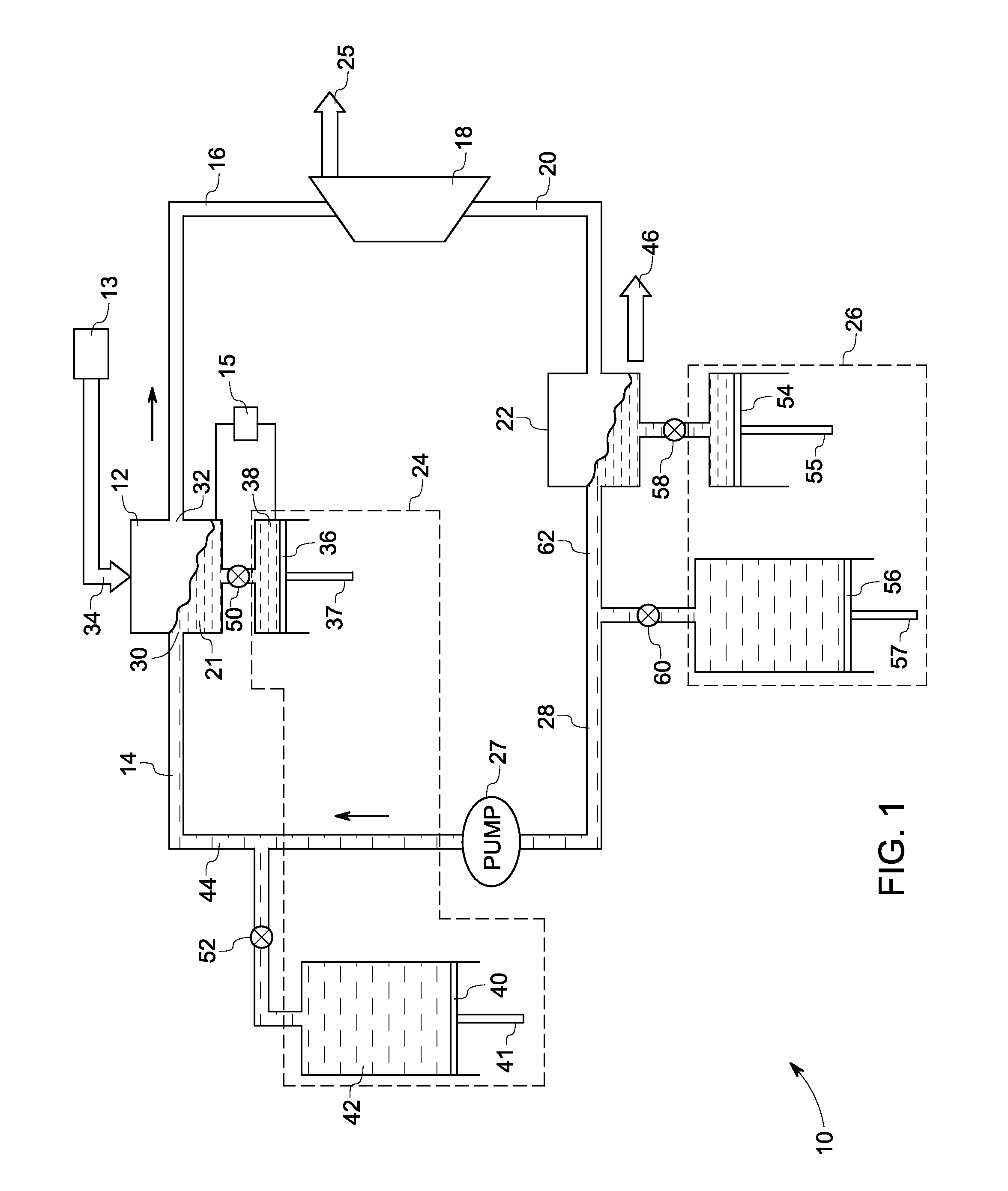
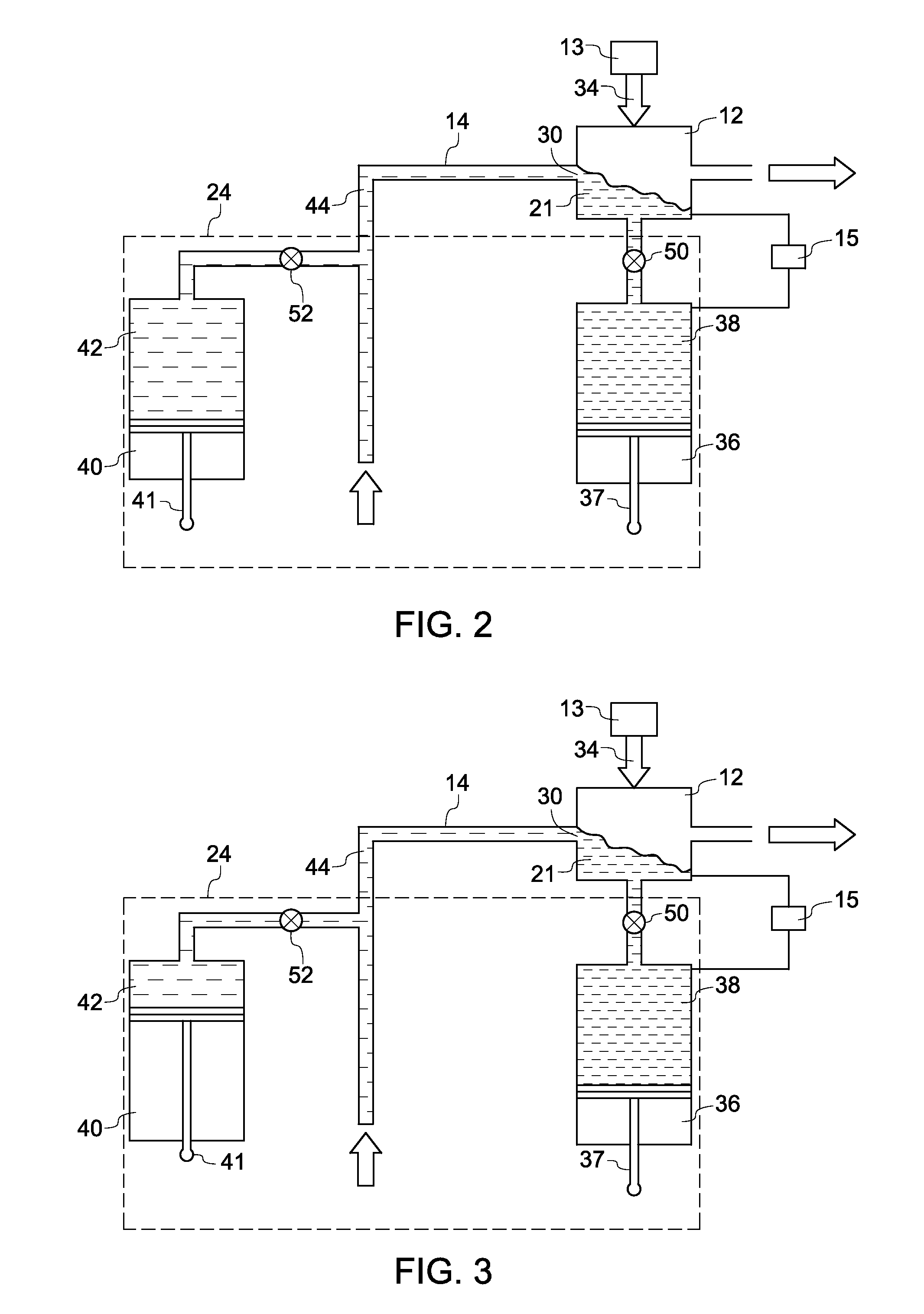
[0014]FIG. 1 represents an exemplary system 10 for power generation using a Rankine Cycle. The system includes a boiler 12 configured to receive heat from an external source 13 and a liquid stream 14 and to generate a vapor stream 16. The power generation system 10 also includes an expander 18 configured to receive the vapor stream 16 and to generate power 25 by rotating the mechanical shaft (not shown) of the expander 18 and an expanded stream 20. A condenser 22 is configured to receive the expanded stream 20 and to generate the liquid stream 14. A supply system is coupled to the boiler 12 or the condenser 22 (with the “or” as used herein meaning either or both) and is configured to control relative concentration of the two liquids in the liquid stream 14 and the vapor stream 16. The liquid stream 14 and the vapor stream 16 along with the vapor and liquid phase within the boiler 12 and condenser 22 form the working fluid of the Rankine cycle shown in FIG. 1.

[0015]The power generati...


PUM


Abstract

A system for power generation includes a boiler configured to receive heat from an external source and a liquid stream and to generate a vapor stream. The liquid stream comprises a mixture of at least two liquids. The system also includes an expander configured to receive the vapor stream and to generate power and an expanded stream. A condenser is configured to receive the expanded stream and to generate the liquid stream. The system further includes a supply system coupled to the boiler or the condenser and configured to control relative concentration of the two liquids in the liquid stream.

Description

BACKGROUND[0001]This invention relates generally to power generation systems using a Rankine cycle. More particularly this invention relates to power generation systems using a Rankine cycle with a mixture of at least two liquids as the working fluid.[0002]Rankine Cycles use a working fluid in a closed cycle to gather heat from a heating source or a hot reservoir by generating a hot gaseous stream that expands through a turbine to generate power. The expanded stream is condensed in a condenser by rejecting the heat to a cold reservoir. The working fluid in a Rankine cycle follows a closed loop and is re-used constantly. The efficiency of Rankine Cycles such as Organic Rankine Cycles (ORCs) in a low-temperature heat recovery application is very sensitive to the temperatures of the hot and cold reservoirs between which they operate. In many cases, these temperatures change significantly during the lifetime of the plant. Geothermal plants, for example, may be designed for a particular ...

Claims


Application Information

Patent Timeline
Patent Type & Authority Patents(United States)
IPC IPC(8): F01K25/06
CPCF01K25/06
Inventor LEHAR, MATTHEW ALEXANDERSTROMBERGER, JOERGFREY, THOMAS JOHANNESAST, GABORBARTLETT, MICHAEL
Owner AI ALPINE US BIDCO INC
Why Eureka
Try Eureka