Wheel clamp

a technology of wheel and clamping rod, which is applied in the field of wheel clamps, can solve the problems of tool loss and inconvenience in use, and achieve the effect of convenient us

Inactive Publication Date: 2009-09-29
WU CHUN HSIEN
View PDF18 Cites 25 Cited by
  • Summary
  • Abstract
  • Description
  • Claims
  • Application Information

AI Technical Summary

Benefits of technology

[0027]1. The present invention uses the second engaging block to mesh with and drive the first engaging block so the rotating unit is able to

Problems solved by technology

This is very inconvenient in use because the lock core A3 has to be disengaged from the cl

Method used


Image

  • Wheel clamp
  • Wheel clamp
  • Wheel clamp

Examples


Embodiment Construction

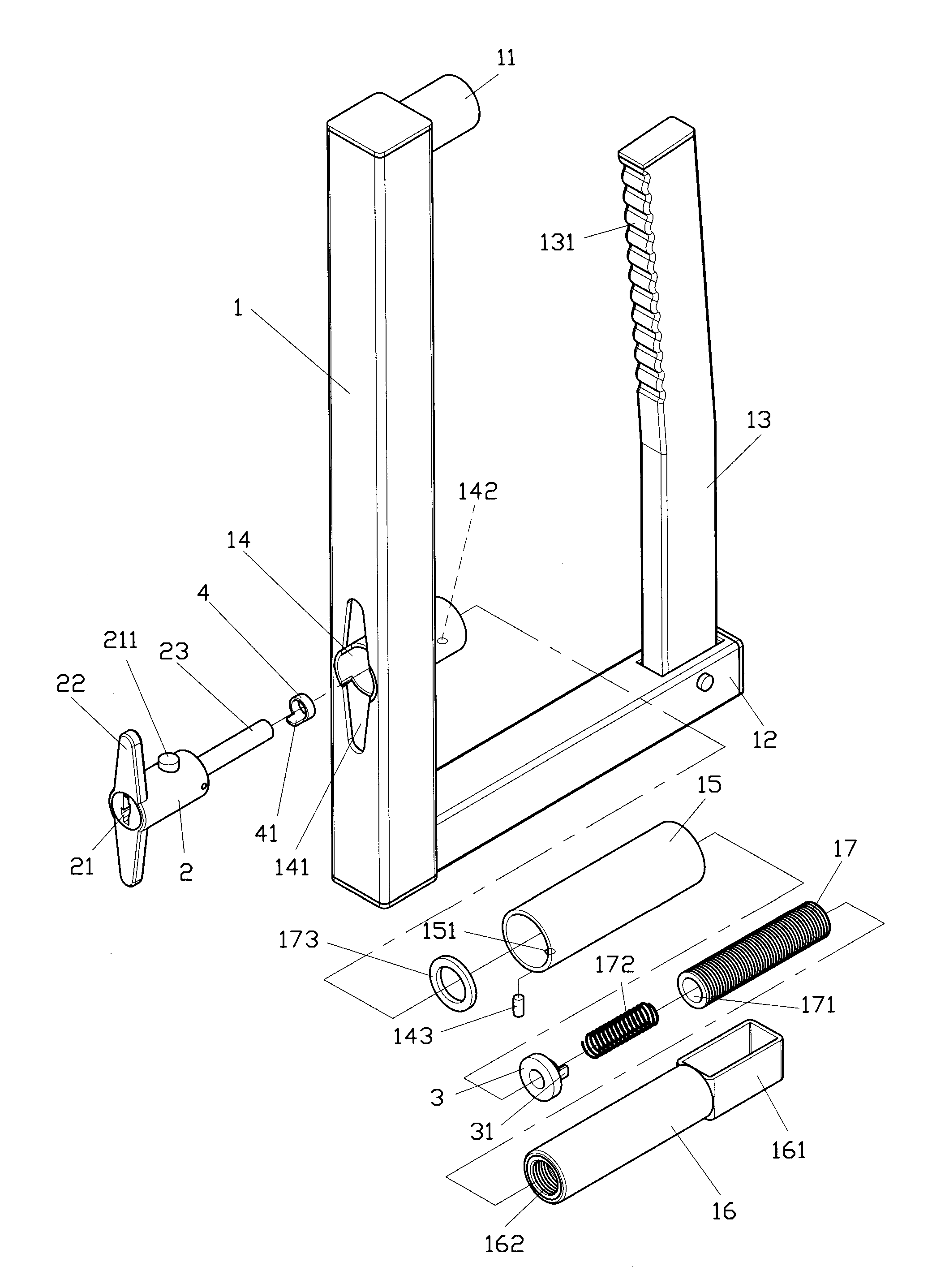
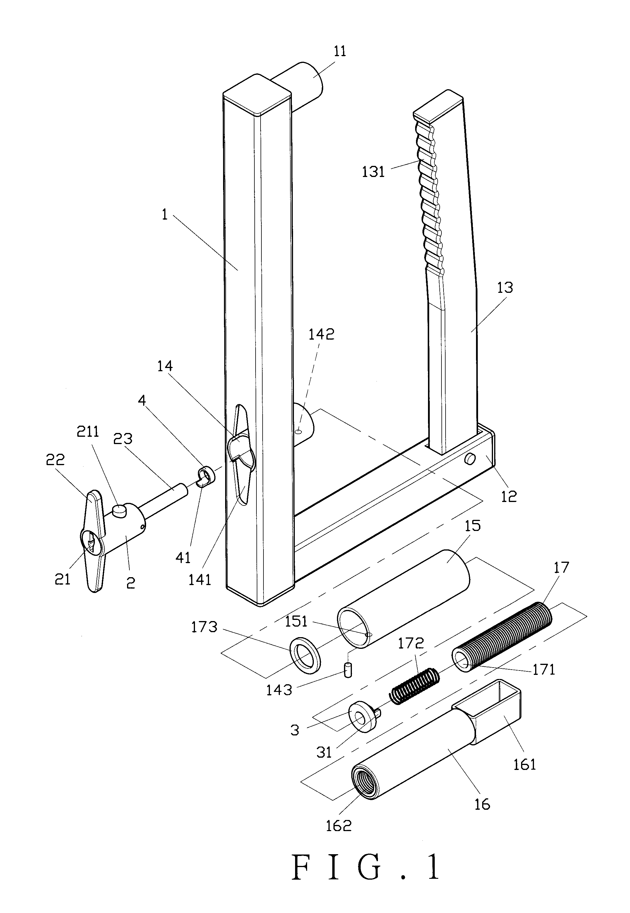
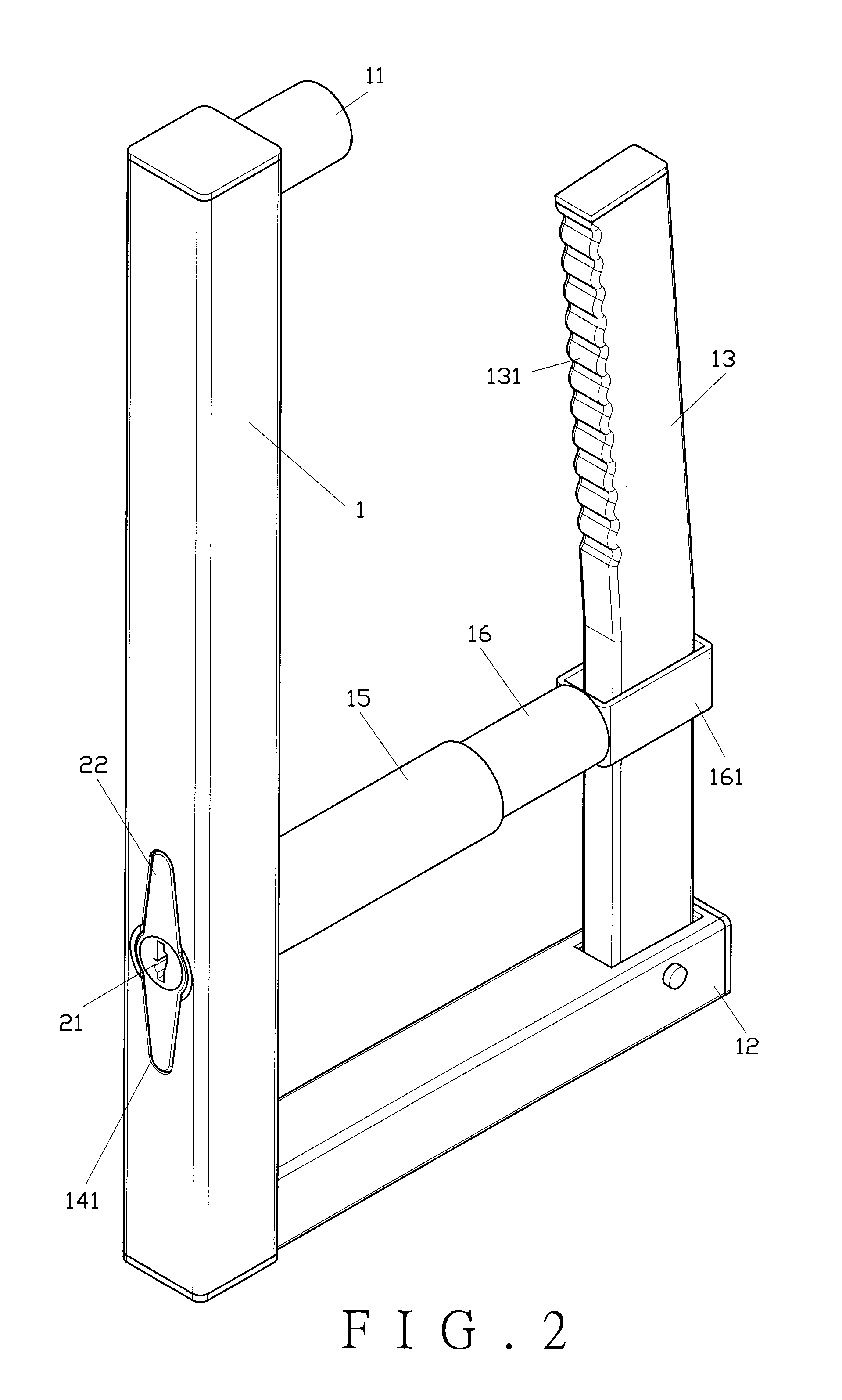
[0043]As shown in FIGS. 1 through 4, a first preferred embodiment of the present invention comprises a clamp body 1, a rotating unit 2, a first engaging member 3, and a second engaging member 4.

[0044]The hollow clamp body 1 is shaped like an English capital letter “L” having two closed ends, and comprises a positioning section 11 at one end and a pivot section 12 at the other end thereof. The pivot section 12 is pivotally connected with a hollow movable rod 13 which has closed upper and lower ends. The movable rod 13 is formed with a rack portion 131 at an upper section thereof. The clamp body 1 is provided with a lock core seat 14 at a middle section thereof and a recess 141 close to one end of the lock core seat 14. The recess 141 is disposed at one side or two opposite sides of the lock core seat 14. The other end of the lock core seat 14 is formed with a first pin hole 142 for insertion of a pin 143 connected to an outer sleeve 15. The outer sleeve 15 is formed with a second pin...


PUM


Abstract

A wheel clamp includes a clamp body, a movable rod pivotally connected to the clamp body, a connecting rod fitted on the movable rod, and a rotating unit disposed in a lock core seat of the clamp body. The connecting rod has a threaded section for connecting with a screw. The rotating unit has a rotating rod to be inserted into an accommodating trough of the screw. A first engaging member is secured to the accommodating trough of the screw. A second engaging member is secured to the rotating rod of the rotating unit. The second engaging member has a second engaging block to mesh with and drive a first engaging block of the first engaging member so the connecting rod is able to be moved relative to the screw.

Description

BACKGROUND OF THE INVENTION[0001]1. Field of the Invention[0002]The present invention relates to a wheel clamp, and more particularly to one having a second engaging member with a second engaging block to mesh with and drive a first engaging block of a first engaging member so a connecting rod is able to be moved relative to a screw. A rotating unit is used to rotate the connecting rod to open a movable rod relative to a clamp body.[0003]2. Description of the Prior Art[0004]As shown in FIG. 15, a conventional wheel clamp disclosed in UK Patent No. GB2179607 comprises an L-shaped clamp body A. One end of the clamp body A is pivotally connected with a movable rod A1. The clamp body A is provided with a connecting rod A2 inserted on the movable rod A1 for moving the movable rod A1. The connecting position of the connecting rod A2 and the clamp body A is provided with a lock core A3 to secure the connecting rod A 2 when the clamp body A is engaged with a wheel. To unlock the wheel clamp...

Claims


Application Information

Patent Timeline
IPC IPC(8): B60R25/00
CPCB60R25/093Y10T70/5841Y10T70/409Y10T70/7576Y10T70/411
Inventor WU, CHUN-HSIEN
Owner WU CHUN HSIEN
Why Eureka
Try Eureka