Device for use with an eye protector

a technology for eye protection and eye protection, which is applied in the direction of headwear caps, goggles, hats, etc., can solve the problems of clumsy use, uncomfortable use of current personal protection enhancement devices, and increased safety hazards for workers, so as to shorten the length, and reduce the force of tension

Inactive Publication Date: 2009-09-29
KIMBERLY-CLARK WORLDWIDE INC
View PDF16 Cites 27 Cited by
  • Summary
  • Abstract
  • Description
  • Claims
  • Application Information

AI Technical Summary

Benefits of technology

[0009]In one aspect of the present invention, there is provided a device for locating a pair of ear engaging members and an eye protector in proximity to a user's head. The device includes a cord including (i) a length with an ear end and an opposite eye end and (ii) a dual mode adjustment member located along the length of the cord between the ear and eye ends. The ear end of the cord includes a left ear end and a right ear end, where each left and right ear end can have one of the pair of ear engaging members joined thereto. The eye end of the cord includes a left eye end and a right eye end, where each left and right eye end has an eye protector connector joined thereto. The dual mode adjustment member is positionable along the length of the cord: (i) to a first mode that adjustably shortens the length of the cord between the adjustment member and the eye end of the cord to thereby provide a force to tension the eye protector connectors toward each other, and (ii) to a second mode that adjustably lengthens the length of the cord between the adjustment member and the eye end of the cord to thereby reduce the force of tension between the eye protector connectors and enable them to be moved further away from each.
[0010]In another aspect of the present invention, there is provided a device for use with an eye protector in proximity to a user's head. The device includes a cord including (i) a length with an ear end and an opposite eye end and (ii) a dual mode adjustment member located along the length of the cord between the ear and eye ends. The ear end of the cord includes a left ear end and a right ear end, where each left and right ear end has an ear engaging member joined thereto. The eye end of the cord includes a left eye end and a right eye end, where each left and right eye end has an eye protector connector joined thereto. The dual mode adjustment member is positionable along the length of the cord: (i) to a first mode that adjustably shortens the length of the cord between the adjustment member and the eye end of the cord to thereby provide a force to tension the eye protector connectors toward each other, (ii) to a second mode that adjustably lengthens the length of the cord between the adjustment member and the eye end of the cord to thereby reduce the force of tension between the eye protector connectors and enable them to be moved further away from each, and (iii) in both the first and second modes the left and right ear ends of the cord are isolated from the eye protector connectors such that (a) the left and right ear ends of the cord can hang from the user while not in use without disturbing operation of the eye protector connectors in use and (b) the eye protector connectors can hang from the user while not in use without disturbing operation of the left and right ear ends of the cord in use.
[0011]In still another aspect of the present invention, there is provided a method for connecting together a pair of ear engaging members and a pair of eye protector connectors. The method includes providing a cord including (i) a length with an ear end and an opposite eye end and (ii) a dual mode adjustment member located along the length of the cord between the ear and eye ends. The ear end of the cord including a left ear end and a right ear end and the eye end of the cord including a left eye end and a right eye end. There is also joining an ear engaging member to each left and right ear end. And, joining an eye protector connector to each left and right eye end. And also, positioning the dual mode adjustment member along the length of the cord to (i) a first mode that adjustably shortens the length of the cord between the adjustment member and the eye end of the cord to thereby provide a force to tension the eye protector connectors toward each other, and (ii) a second mode that adjustably lengthens the length of the cord between the adjustment member and the eye end of the cord to thereby reduce the tension between the eye protector connectors and enable them to be moved further away from each other.
[0012]In yet another aspect of the present invention there is provided a method for locating a pair of ear engaging members with an eye protector in proximity to a user's head. This includes providing a cord including (i) a length with an ear end and an opposite eye end and (ii) a dual mode adjustment member located along the length of the cord between the ear and eye ends. The ear end of the cord including a left ear end and a right ear end and the eye end of the cord including a left eye end and a right eye end. This further includes joining an ear engaging member to each left and right ear end. And, joining an eye protector connector to each left and right eye end. And further, joining the eye protector connectors to the eye protector. And also, positioning the dual mode adjustment member along the length of the cord to (i) a first mode that adjustably shortens the length of the cord between the adjustment member and the eye end of the cord to thereby provide a force to tension the eye protector connectors toward each other and thereby secure the eye protector to the user's head, and (ii) a second mode that adjustably lengthens the length of the cord between the adjustment member and the eye end of the cord to thereby reduce the tension between the eye protector connectors and enable them to be moved further away from each and thereby unsecure the eye protector from the user's head.

Problems solved by technology

The lack of worker compliance with safety rules is exacerbated by the fact that currently available personal protection enhancement devices are often uncomfortable, clumsy to use, to limited in their use, and / or perform poorly.

Method used


Image

  • Device for use with an eye protector
  • Device for use with an eye protector
  • Device for use with an eye protector

Examples


Embodiment Construction

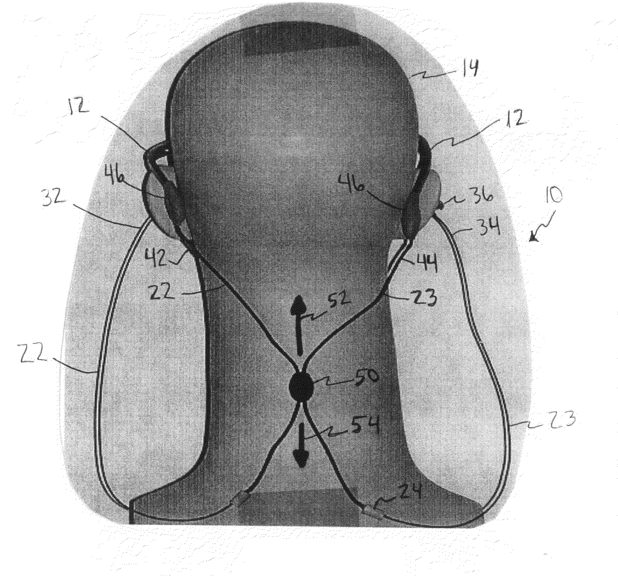
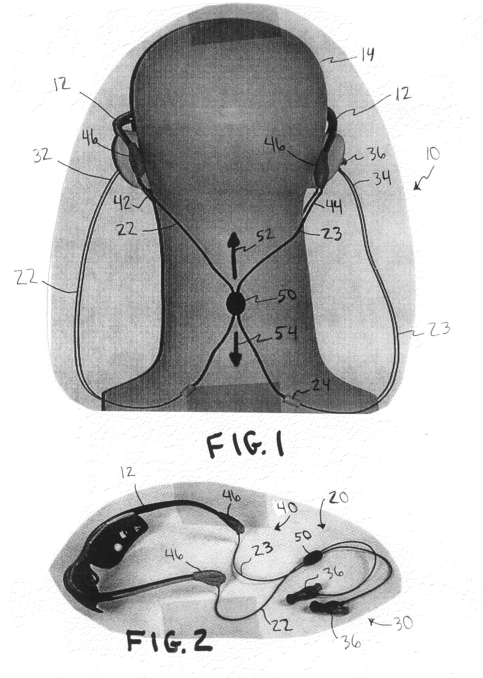
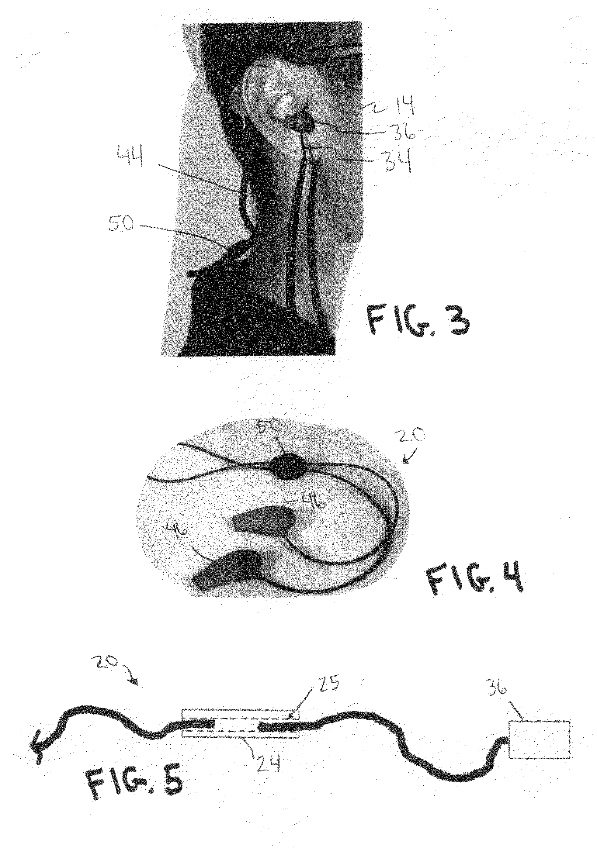
[0022]Referring now to the drawings and in particular FIGS. 1-4 for example, there is depicted a device 10 for locating a pair of ear engaging members 36 and an eye protector 12 in proximity to a user's head 14. Device 10 includes a cord 20. The cord has a length with an ear end 30 and an opposite eye end 40, and a dual mode adjustment member 50 located along the length of the cord between the ear and eye ends. Ear end 30 of the cord has a left ear end 32 and a right ear end 34, and each left and right ear end can have one of the pair of ear engaging members 36 joined thereto. Eye end 40 of the cord has a left eye end 42 and a right eye end 44, and each left and right eye end has an eye protector connector 46 joined thereto.

[0023]Dual mode adjustment member 50 is positionable along the length of cord 20 in two modes. There is a first mode 52 that adjustably shortens the length of the cord between adjustment member 50 and eye end 40 of the cord to thereby provide a force to tension e...


PUM


Abstract

A device and method for locating a pair of ear engaging members and an eye protector in proximity to a user's head. This includes a cord with a length and a dual mode adjustment member located along the length of the cord. An ear end of the cord can have a pair of ear engaging members joined thereto. An eye end of the cord has a pair of eye protector connectors joined thereto. The dual mode adjustment member is positionable along the length of the cord to a first mode and to a second mode shortens that, respectively, lengths or shortens the cord between the adjustment member and the eye end of the cord.

Description

BACKGROUND OF THE INVENTION[0001]The present invention relates generally to devices for locating equipment about a user, and more particularly to such devices being used to enhance the features of personal safety devices worn by a user about their head, such as eye protectors and ear engaging members (e.g., hearing protectors).[0002]The need for locating equipment about a user, and in particular their head has long been recognized among those concerned with convenience as well as health and safety issues. However, most experts in this field would acknowledge that this effort has room for needed improvements. For example, personal protective devices have proliferated, yet there still remain needs to enhance convenience and / or use compliance. Workers who should use these devices often do not, or use them only under duress from their employers. The lack of worker compliance with safety rules is exacerbated by the fact that currently available personal protection enhancement devices are...

Claims


Application Information

Patent Timeline
Patent Type & Authority Patents(United States)
IPC IPC(8): G02C3/00
CPCA61F9/027A61F9/029G02C11/00G02C3/003A61F11/12
Inventor PURCELL, RICKY WAYNE
Owner KIMBERLY-CLARK WORLDWIDE INC
Why Eureka
Try Eureka