Maglatch mechanism for use in lighting control pod

a technology of magnets and control pods, which is applied in the direction of circuit-breaking switches, relays, protective switches, etc., can solve the problems of increasing the size of the required mechanism, worm-gear motor design producing a loud noise, and worm-gear design being prone to slippage and failure of the mechanism

Inactive Publication Date: 2009-09-29
SIEMENS ENERGY & AUTOMATION INC
View PDF8 Cites 34 Cited by
  • Summary
  • Abstract
  • Description
  • Claims
  • Application Information

AI Technical Summary

Benefits of technology

[0015]A wrist pin connects the contact arm and the armature, the wrist pin being disposed in a clearance hole in at least one of the contact arm and the armature, permitting relative movement thereof. The retracted position of the armature results in the stable open position of the contact assembly.

Problems solved by technology

Those factors can increase the size of the required mechanism.
The worm-gear motor design produces a loud noise due to the operation of the DC motor.
The worm-gear design is furthermore prone to slippage and failure of the mechanism.
The multi-linkage solenoid driven mechanism has the disadvantage of requiring several points of rotation, and numerous moving parts.
Given that a lighting control device is expected to cycle 50,000-100,000 times during its life, the use of multi-spring assemblies increases the risk that frictional wear will cause the mechanism to fail during its intended life.
Such a design increases the mass of the circuit breaker mechanism and thus results in parasitic loading of the breaker mechanism, degrading performance.
Because the breaker handle requires greater force, the actuating device must be a larger and higher-cost unit.
To the inventors' knowledge, no such design is currently available.

Method used


Image

  • Maglatch mechanism for use in lighting control pod
  • Maglatch mechanism for use in lighting control pod
  • Maglatch mechanism for use in lighting control pod

Examples


Embodiment Construction

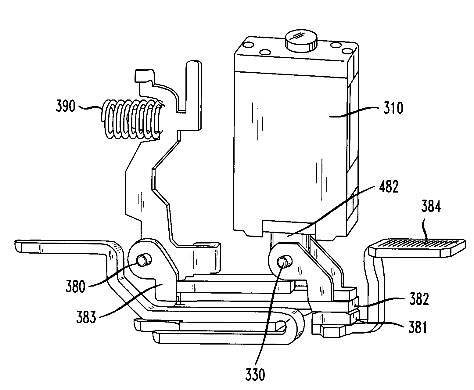
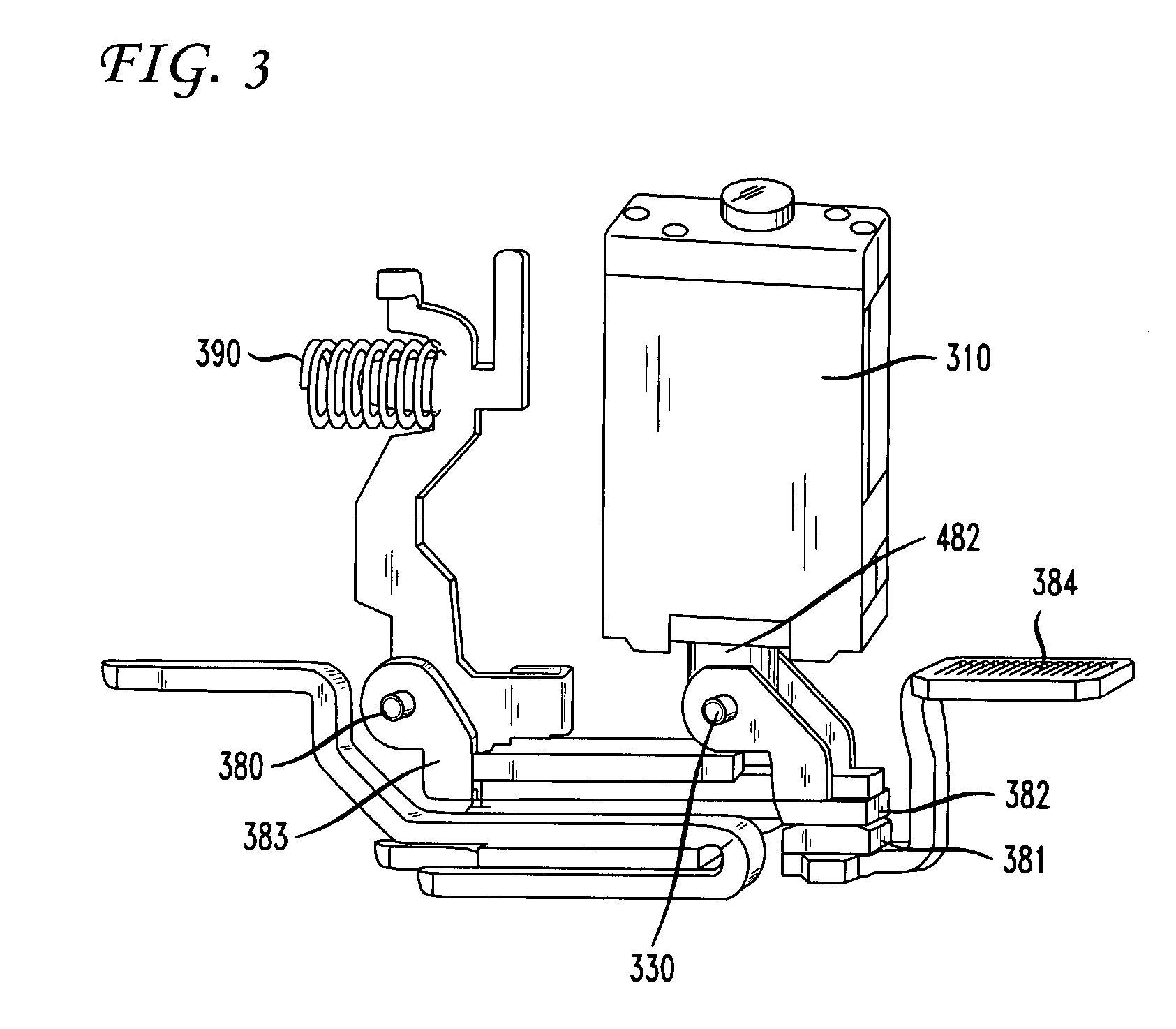
[0034]The present invention is a method and apparatus for opening and closing a pair of contacts in a circuit control pod such as a lighting control pod. A magnetic latch solenoid mechanism, or “maglatch,” is employed with a spring that is not located in close proximity to the contacts or to the maglatch in order to provide bi-stable operation.

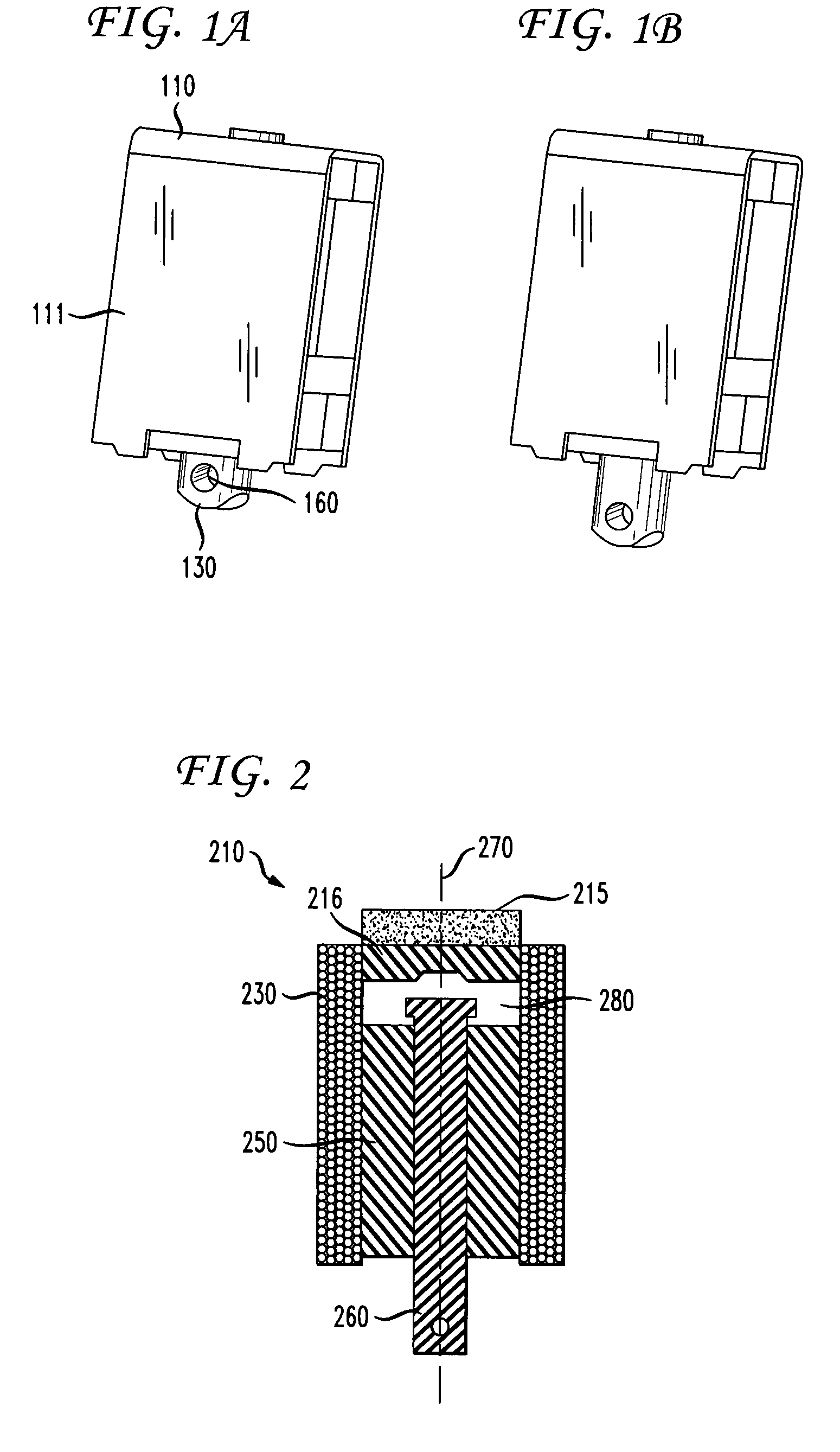
[0035]A maglatch is a variation of a solenoid in which a permanent magnet is added to a solenoid. This component allows for translation of electrical signals to a mechanical motion. A maglatch used in a preferred embodiment of the present invention is shown in FIGS. 1A and 1B. The maglatch includes a maglatch housing 110 and a plunger 160. The plunger 160 may have a wrist pin hole 130 for accepting a wrist pin as described in more detail below.

[0036]A schematic cross sectional view of a maglatch 210 in accordance with the invention is shown in FIG. 2. A plunger 260 extends from the maglatch 210 and corresponds to the plunger 160 of FIG. 1A. Ot...


PUM


Abstract

An electrical contact assembly includes a magnetic latch solenoid for actuating a moveable contact of a contact pair. The magnetic latch solenoid includes a magnet that latches the contact assembly in an open position, and a coil that moves an armature to the latched position under current in one polarity, and disrupts the permanent magnet field to release the armature from the latched position under current in a reverse polarity. A spring biases the contacts to the closed position. The spring is separate from the magnetic latch solenoid. The contact assembly may also include a printed circuit board for providing pulses to the coil to operate the assembly. The contact assembly is part of a remote operated circuit breaker assembly.

Description

CROSS REFERENCE TO RELATED APPLICATIONS[0001]This application claims the benefit of priority from U.S. Provisional Patent Application Ser. No. 60 / 830,535 entitled “Maglatch Mechanism for Use in Lighting Control Pod,” filed on Jul. 13, 2006, the contents of which are hereby incorporated by reference herein in their entirety.FIELD OF THE INVENTION[0002]The present invention relates generally to an improved remote controlled circuit breaker and circuit control assembly, and more specifically to remote controlled contacts having a magnetic latch mechanism providing a bi-stable operation.BACKGROUND OF THE INVENTION[0003]There has been an increasing demand for remotely controllable circuit breaker assemblies that can reciprocate between an open circuit and a closed circuit in response to a remotely generated command. One advantageous application for such circuit breaker assemblies is in control panelboards that are used for automated control systems such as building management systems. Bu...

Claims


Application Information

Patent Timeline
Patent Type & Authority Patents(United States)
IPC IPC(8): H01H75/00H01H9/20
CPCH01H51/2209H01H51/01H01H89/06H01H71/66H01H73/02
Inventor DEBOER, JOHNMCCOY, BRIAN TIMOTHY
Owner SIEMENS ENERGY & AUTOMATION INC
Why Eureka
Try Eureka