Hinge

a technology of hinges and hinges, applied in the field of hinges, can solve the problems of reducing the rotation speed of the rotatable cam, and affecting the operation of the foldable electronic devi

Inactive Publication Date: 2009-10-06
CHENG UEI PRECISION IND CO LTD
View PDF16 Cites 22 Cited by
  • Summary
  • Abstract
  • Description
  • Claims
  • Application Information

AI Technical Summary

Benefits of technology

[0007]Accordingly, an object of the present invention is to provide a hinge for smoothly opening or closing a foldable electronic device.
[0009]As described above, the design of the present invention provides a damper mating with the rotatable cam and the cap to restrain the rotation speed of the rotatable cam. Therefore, the foldable electronic device with the hinge can be opened or closed much securer.

Problems solved by technology

But it is not convenient to carry the portable electronic device with a big screen.
That is, the required big screen and the required small size of the portable electronic device are contrary.
However, the process that the compressed spring 400 drives the foldable electronic device opened fully is too quickly.
Therefore, an impact is produced between the cover and the main body, so the foldable electronic device is easy to be broken or damaged.

Method used


Image

  • Hinge
  • Hinge
  • Hinge

Examples


Embodiment Construction

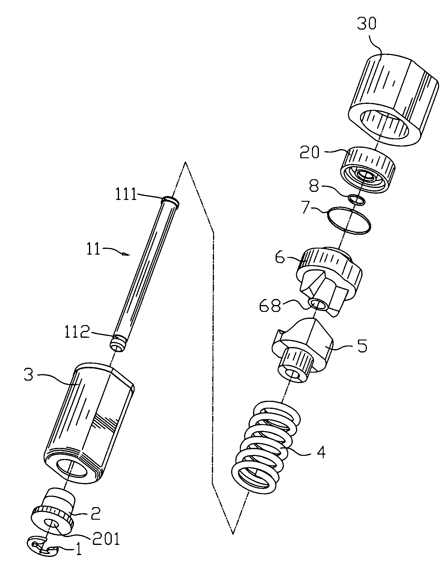
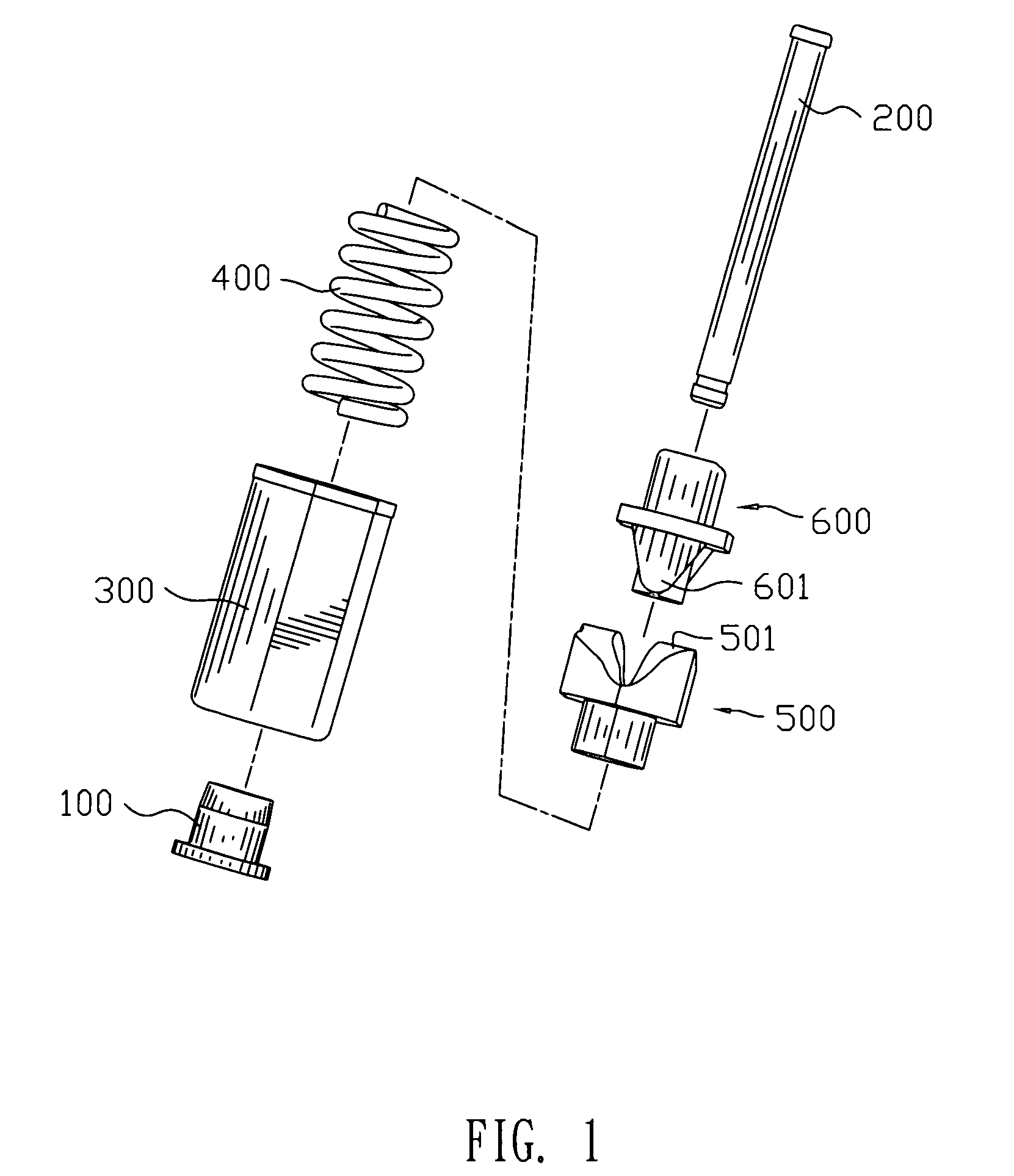
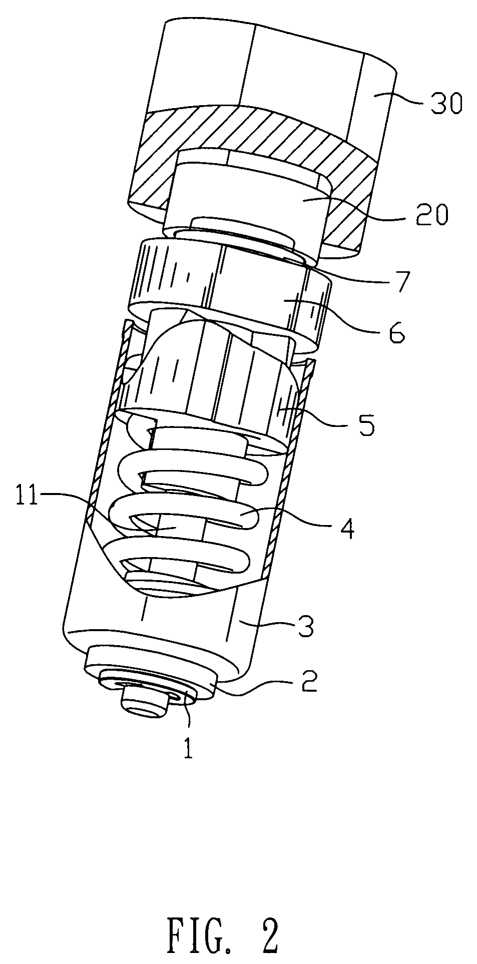
[0019]Referring to FIG. 2 and FIG. 3, a hinge in accordance with the present invention includes a housing 3 which is hollow. Both ends of the housing 3 communicate with the outside. A stopper 2 is plugged up one end of the housing 3, and the stopper 2 defines a through-hole 201 passing therethrough. A torsion-bar spring 4 and a sliding cam 5 are slideably received in the housing 3. One end of the spring 4 is fastened around the stopper 2 that protrudes into an inner of the housing 3, and an opposite end of the spring 4 is fixed on the sliding cam 5. A shaft 11 runs through the sliding cam 5, the spring 3 and the through-hole 201 of the stopper 2 in turn. One end of the shaft 11 defines a notch 112 around thereof and the notch 112 is exposed out of the stopper 2. A limiting ring 1 is provided to locate the end of the shaft 11 on the stopper 2. The limiting ring 1 is substantially E-shaped and defines a gap thereon. The limiting ring 1 is locked in the notch 112 of the shaft 11 and is...


PUM


Abstract

A hinge includes a housing. A stopper plugging up one end of the housing defines a through-hole. A sliding cam slideably received in the housing defines concave portions on a top surface thereof and an axial hole. A rotatable cam has a base portion extending downward to form pushing portions disposed in the concave portions. The base portion defines a receiving hole. A top surface of the base portion protrudes upward and defines a stepped portion. A spring is slideably received in the housing. One end of the spring is fixed on the sliding cam and the other end of the spring is fastened around the stopper. A shaft received in the housing runs through the axial hole, the spring and the through-hole. An end of the shaft is fixed with the stopper, and an opposite end of the shaft is received in the receiving hole. A damper has a top wall extending downward to form an enclosure. A top surface of the top wall protrudes upward to form a preventing block. A bottom surface of the top wall extends downward to form mounting portions. The mounting portions are encircled in the enclosure and match with the stepped portion. A cap rotatablely receiving the damper defines an accommodating space. A part of the accommodating space forms a restraining portion.

Description

BACKGROUND OF THE INVENTION[0001]1. Field of the Invention[0002]The present invention relates to a hinge, and more particularly to a hinge for smoothly opening or closing a foldable electronic device.[0003]2. The Related Art[0004]As the development of modern mobile communication industry, portable electronic devices such as cellular phones, notebook computers and personal digital assistants, etc., become more and more popular. Thereinto, many portable electronic devices have a function of displaying image. In order to display image as distinctly as possible, so screens of the portable electronic devices need to be designed as big as possible. But it is not convenient to carry the portable electronic device with a big screen. That is, the required big screen and the required small size of the portable electronic device are contrary. To solve the problem, foldable electronic devices have been developed. Generally, the foldable electronic device has a cover which is usually used as a s...

Claims


Application Information

Patent Timeline
Patent Type & Authority Patents(United States)
IPC IPC(8): E05F1/08
CPCG06F1/1616G06F1/1681E05D11/1078E05F1/1223E05Y2201/21E05Y2201/254E05Y2201/266Y10T16/5387Y10T16/2771Y10T16/540255E05Y2900/606
Inventor YIN, TE-HUNGYANG, SHAN-YILIN, MING-HANLIANG, WEI-JIACHIEN, CHIH-HENG
Owner CHENG UEI PRECISION IND CO LTD
Why Eureka
Try Eureka