Wear assembly

a technology of wear and assembly, applied in the direction of soil shifting machines/dredgers, constructions, etc., can solve the problems of harsh conditions in the excavating buckets of earth-moving equipment, and achieve the effects of convenient use, increased safety, and convenient manufacturing

Inactive Publication Date: 2009-10-06
ESCO CORP
View PDF96 Cites 35 Cited by
  • Summary
  • Abstract
  • Description
  • Claims
  • Application Information

AI Technical Summary

Benefits of technology

[0004]The present invention pertains to an improved wear assembly for protecting an excavating bucket from wear, which is secure, stable, easy to use, readily manufactured, and provides increased safety. The present invention further eliminates any need for holes to be formed in the lip.
[0005]In accordance with one aspect of the invention, the wear assembly includes a wear member provided with a connector in the form of a tongue or slot which has rails or grooves, respectively, to couple with a complementary connector on a boss fixed to the bucket. The rails or grooves are formed with a curved and / or narrowing configuration to ease installation and removal of the wear member, permit the use of wings to better protect adjacent parts, and better resist some loads.
[0006]In accordance with another aspect of the invention, the wear member includes an interior which wraps about the front edge of the bucket and a boss fixed to the bucket. The interior has a first recess with a first set of opposed sidewalls to receive an upstanding support on a boss, and a second recess with a second set of opposed sidewalls spaced farther apart than the first set of opposed sidewalls to receive the sides of the boss. By using two sets of recesses, the wear member is more stably mounted and better able to resist side loads.
[0007]In accordance with another aspect of the invention, the wear member includes laterally extending wings to overlie adjacent parts, e.g., an adapter, attached to the lip to provide additional protection.

Problems solved by technology

Excavating buckets for earth working equipment are typically subjected to harsh conditions.

Method used


Image

  • Wear assembly
  • Wear assembly
  • Wear assembly

Examples


Embodiment Construction

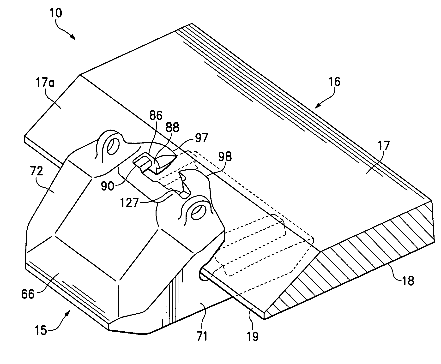
[0020]The present invention pertains to a wear assembly 10 for an excavating bucket. While wear assembly 10 is particularly suited for securing a wear member 15 in the form of a shroud to a lip of a bucket, it could also be used to secure other kinds of wear members (e.g., wings or adapters) to the bucket. In a typical bucket, lip 16 includes an inner face 17, an outer face 18 and a front edge 19. Although the illustrated lip (FIG. 1) shows the inner face 17 with a ramp surface 17a, the invention can be used with other kinds of lips.

[0021]The invention is at times described in relative terms, such as forward, rearward, up, down, vertical, horizontal, etc. to ease understanding of the invention. These terms are generally to be considered relative to the orientation of the components in FIG. 1 (unless otherwise noted), and are not to be considered limitations on the invention. As can be appreciated, the wear member can be used and oriented in a variety of ways.

[0022]A boss or base 20 ...


PUM


Abstract

A wear assembly to protect the front edge of an excavating bucket, which is secure, stable, easy to use, readily manufactured, and provides increased safety, and which eliminates any need for holes to be formed in the lip. The wear assembly includes a wear member that has a pair of legs to straddle the front edge of the bucket. One of the legs defines an axial slot, which has opposing grooves for receiving rails of a boss fixed to the bucket. The grooves narrow in a forward direction to permit easier installation and removal of the wear member, to permit use of side wings without interference from adjacent wear parts, and to enable enhanced resistance under some loads.

Description

[0001]This application is a continuation-in-part of co-pending U.S. patent application Ser. No. 11 / 529,447 filed Sep. 28, 2006, which in turn is a divisional application of U.S. patent application Ser. No. 10 / 812,348 filed Mar. 30, 2004.THE FIELD OF THE INVENTION[0002]The present invention pertains to a wear assembly for an excavating bucket.THE BACKGROUND OF THE INVENTION[0003]Excavating buckets for earth working equipment are typically subjected to harsh conditions. A series of wear members are usually provided along the lip of the bucket to improve the digging operation and protect against wear. Wear members have in the past been welded or mechanically secured in many different ways. Nevertheless, there is a need for an improved wear assembly in these environments.SUMMARY OF THE INVENTION[0004]The present invention pertains to an improved wear assembly for protecting an excavating bucket from wear, which is secure, stable, easy to use, readily manufactured, and provides increased...

Claims


Application Information

Patent Timeline
Patent Type & Authority Patents(United States)
IPC IPC(8): E02F9/28
CPCE02F9/28E02F9/2883E02F9/2833E02F9/2825
Inventor JONES, LARREN F.JONES, LEGAL REPRESENTATIVE, DANIEL THOMAS
Owner ESCO CORP
Why Eureka
Try Eureka