Motorized surgical handpiece

a surgical handpiece and motorized technology, applied in the field can solve the problems of motorized surgical handpieces, couplings are particularly susceptible to problems, and become trapped in the blind end of the cavity

Inactive Publication Date: 2009-10-06
ROGERS WILLIAM G
View PDF31 Cites 793 Cited by
  • Summary
  • Abstract
  • Description
  • Claims
  • Application Information

AI Technical Summary

Problems solved by technology

Depending on the cutting operation to be performed and the type of anatomical tissue to be cut with the cutter, it is oftentimes necessary for the output shaft to rotate the surgical tool at considerably high speeds.
Motorized surgical handpieces that have a solid output shaft and a separate coupling on the output shaft for receiving a shank of the surgical tool in a cavity of the coupling are particularly susceptible to problems arising from the entry of debris into the coupling.
During the cutting operation, debris may travel along the shank of the surgical tool toward the coupling and may enter the cavity of the coupling around the shank of the surgical tool.
The blind end of the cavity within the coupling undesirably promotes the accumulation of debris in the coupling.
It is unavoidable, however, that during the cleaning process some of the debris will be pushed by the brush further into the cavity and will become trapped in the blind end of the cavity.
As a result of repeated use and cleaning of the handpiece over time, debris trapped in the cavity of the coupling will build up to the point where the shank of the surgical tool cannot be properly maintained in the cavity of the coupling or be properly driven by the output shaft.
Another approach to cleaning the cavity of debris involves disassembling the handpiece, which ordinarily must be performed at the manufacturer's facility at considerable inconvenience, time and expense.
An additional drawback to conventional motorized surgical handpieces relates to their inability to effectively seal the interior of the handpiece from foreign substances including contaminants, such as the debris generated by the cutting operation, and cleaning substances.
Consequently, the life of the motor in many motorized surgical handpieces is often prematurely shortened due to the exposure to foreign substances such as contaminants and cleaning substances, especially given the need for the handpieces to be sterilized to medical standards after each use.
In motorized surgical handpieces where seals are provided on the output shaft, the seals produce friction that undesirably limits the rotational speed of the output shaft and, therefore, the rotational speed of the surgical tool.
The Horner, Alexson et al and Carusillo et al patents disclose motorized handpieces, but the handpieces do not incorporate non-contacting seals to seal the motors and the interiors of the handpieces from foreign substances.

Method used


Image

  • Motorized surgical handpiece
  • Motorized surgical handpiece
  • Motorized surgical handpiece

Examples


Embodiment Construction

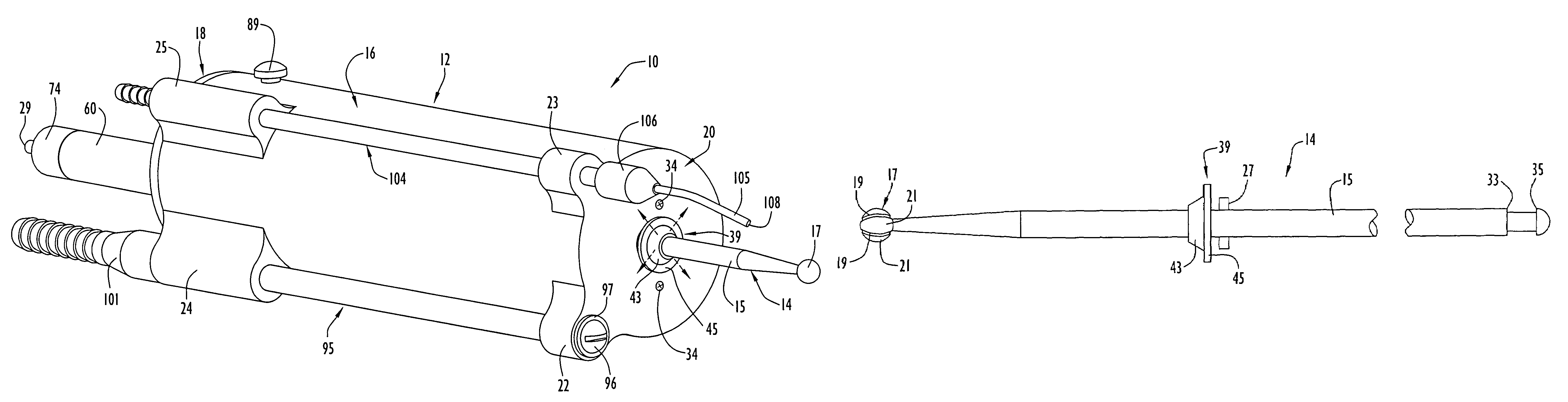
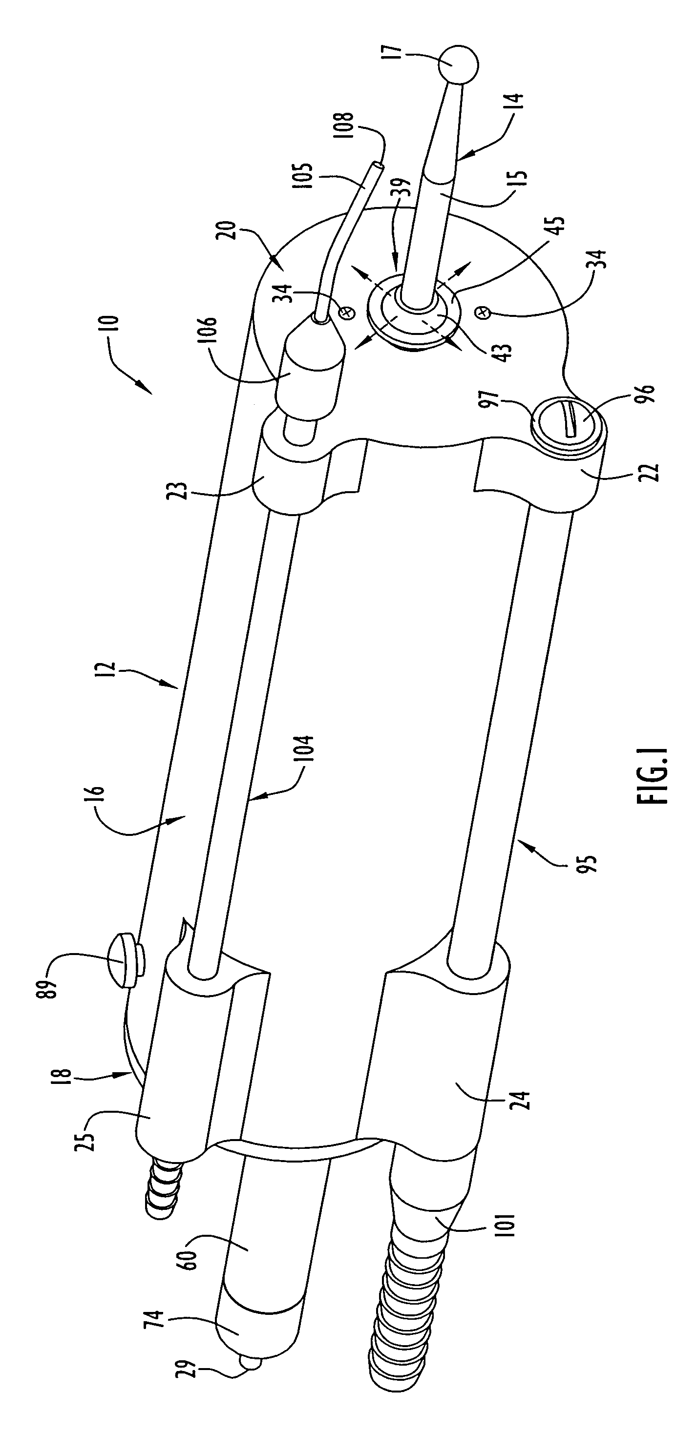
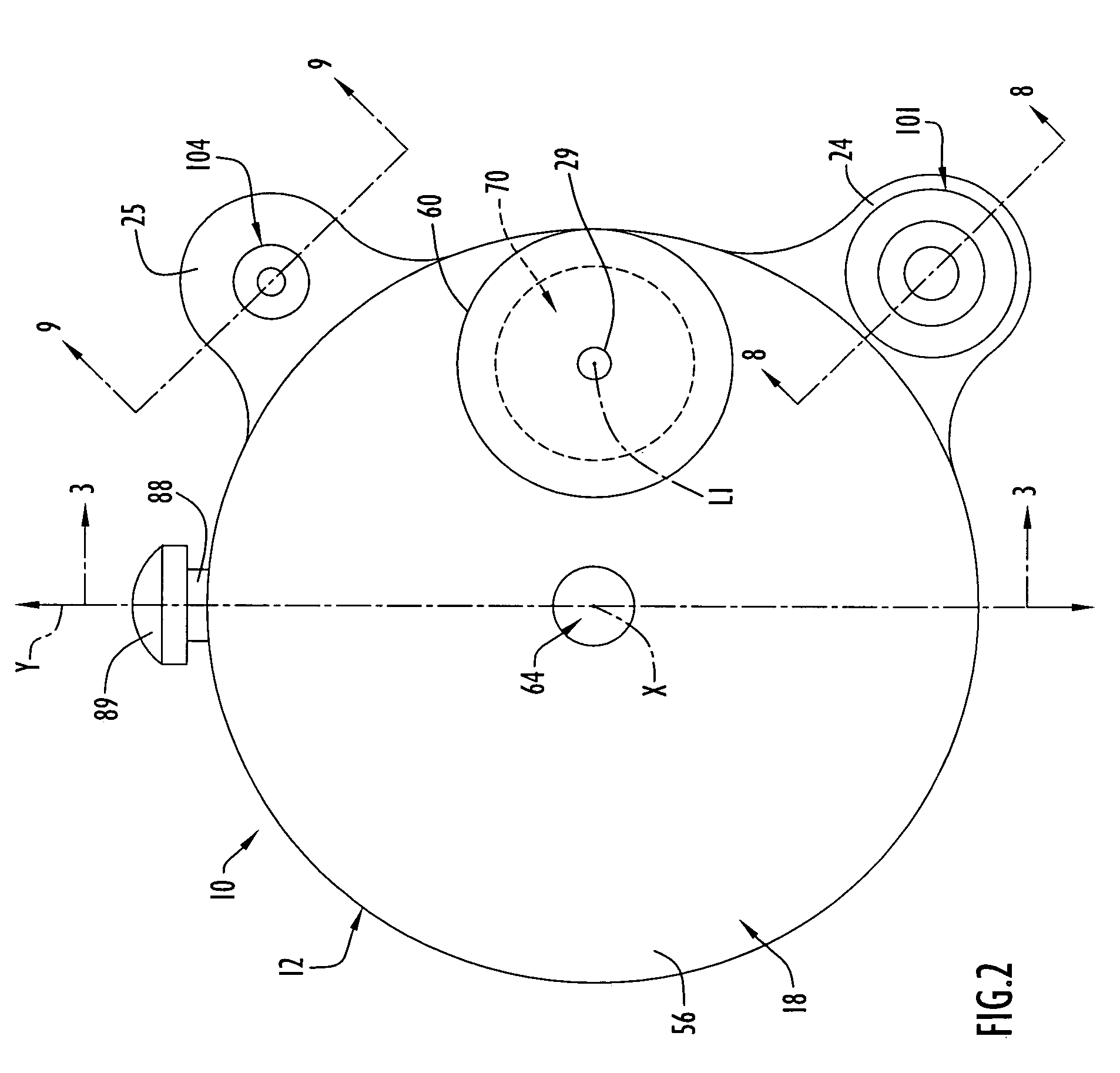
[0022]A motorized surgical instrument 10 incorporating a motorized surgical handpiece 12 according to the present invention is depicted in FIGS. 1-3. The motorized surgical instrument 10 comprises the motorized surgical handpiece 12 and a surgical tool 14 removably coupled to the handpiece 12 to be driven in rotation by a motor driven output shaft of the handpiece 12. The handpiece 12, as best shown in FIGS. 1-4, has a housing comprising a body 16 and an end cap 18 mounted on a rearward end of the body 16. The body 16 has a central longitudinal axis X, an interior, a forward end closed by a forward end wall 20, an open rearward end closed by end cap 18 to enclose the interior, a first forward radial extension 22, a first rearward radial extension 24, a second forward radial extension 23 and a second rearward radial extension 25. The body 16 has an external configuration conducive to being grasped by the hand of a user, the body 16 having a cylindrical external configuration with a c...


PUM


Abstract

A motorized surgical handpiece comprises a housing enclosing an interior containing a motor and an output shaft for being driven in rotation by the motor. The output shaft has a central longitudinal axis, a bore extending therethrough for receiving a shank of a surgical tool to be rotatably driven by the output shaft, a forward end portion extending forwardly beyond the motor and a rearward end portion extending rearwardly beyond the motor. The housing has a continuous lumen extending entirely therethrough formed in part by the output shaft bore for insertion of a bore brush through the lumen for cleaning when the surgical tool is removed from the handpiece. The handpiece has forward and rearward labyrinth seals comprising rotor components respectively attached to the forward and rearward end portions of the output shaft for rotation in corresponding stator components with there being a labyrinthine clearance between each rotor component and its stator component to receive pressurized air during use and during cleaning of the handpiece to avoid the entry of contaminants.

Description

BACKGROUND OF THE INVENTION[0001]1. Field of the Invention[0002]The present invention relates generally to motorized surgical handpieces including pressurized labyrinth seals and a hollow, motor driven rotatable output shaft with a through bore for receiving a shank of a surgical tool in driving engagement.[0003]2. Brief Discussion of the Related Art[0004]Motorized surgical handpieces are commonly used to rotatably drive surgical tools, such as drills and burs, to perform a cutting operation on anatomical tissue at a surgical site. Motorized surgical handpieces typically include a motor contained in the interior of a housing of the handpiece and an output shaft driven by the motor in rotation for being coupled to a shank of a surgical tool in driving engagement. The surgical tool typically includes the shank and a cutter carried by the shank to perform a cutting operation on anatomical tissue when the shank is rotatably driven by the output shaft. Depending on the cutting operation ...

Claims


Application Information

Patent Timeline
Patent Type & Authority Patents(United States)
IPC IPC(8): A61B17/32
CPCA61B17/162A61B17/1622A61B17/1628A61B17/320758A61B17/32002A61B17/1646A61B2217/007A61B19/34A61B2017/0046A61B2019/4868A61B90/70A61B2090/0813
Inventor ROGERS, WILLIAM G.
Owner ROGERS WILLIAM G
Why Eureka
Try Eureka