Network traffic synchronization and data compression in redundant network topologies

a network traffic and data compression technology, applied in data switching networks, frequency-division multiplexes, instruments, etc., can solve problems such as and affecting data transfer speed

Active Publication Date: 2009-10-06
CA TECH INC
View PDF16 Cites 74 Cited by
  • Summary
  • Abstract
  • Description
  • Claims
  • Application Information

AI Technical Summary

Problems solved by technology

While there are certain perceived advantages, this characteristic has the consequence of juxtaposing very high-speed packets and very low-speed packets in potential conflict and produces certain inefficiencies.
Certain loading conditions degrade performance of networked applications and can even cause instabilities which could lead to overloads that could stop data transfer temporarily.
The problem with this approach is that, while network access is preserved, there is no failover mechanism to control or optimize network traffic while the application traffic management device 130 remains down.
While the hot standby feature is suitable in shared Ethernet environments, the use of Ethernet LAN switches in more modern enterprise networks has presented further challenges.
Furthermore, many enterprise network architectures feature

Method used


Image

  • Network traffic synchronization and data compression in redundant network topologies
  • Network traffic synchronization and data compression in redundant network topologies
  • Network traffic synchronization and data compression in redundant network topologies

Examples


Embodiment Construction

)

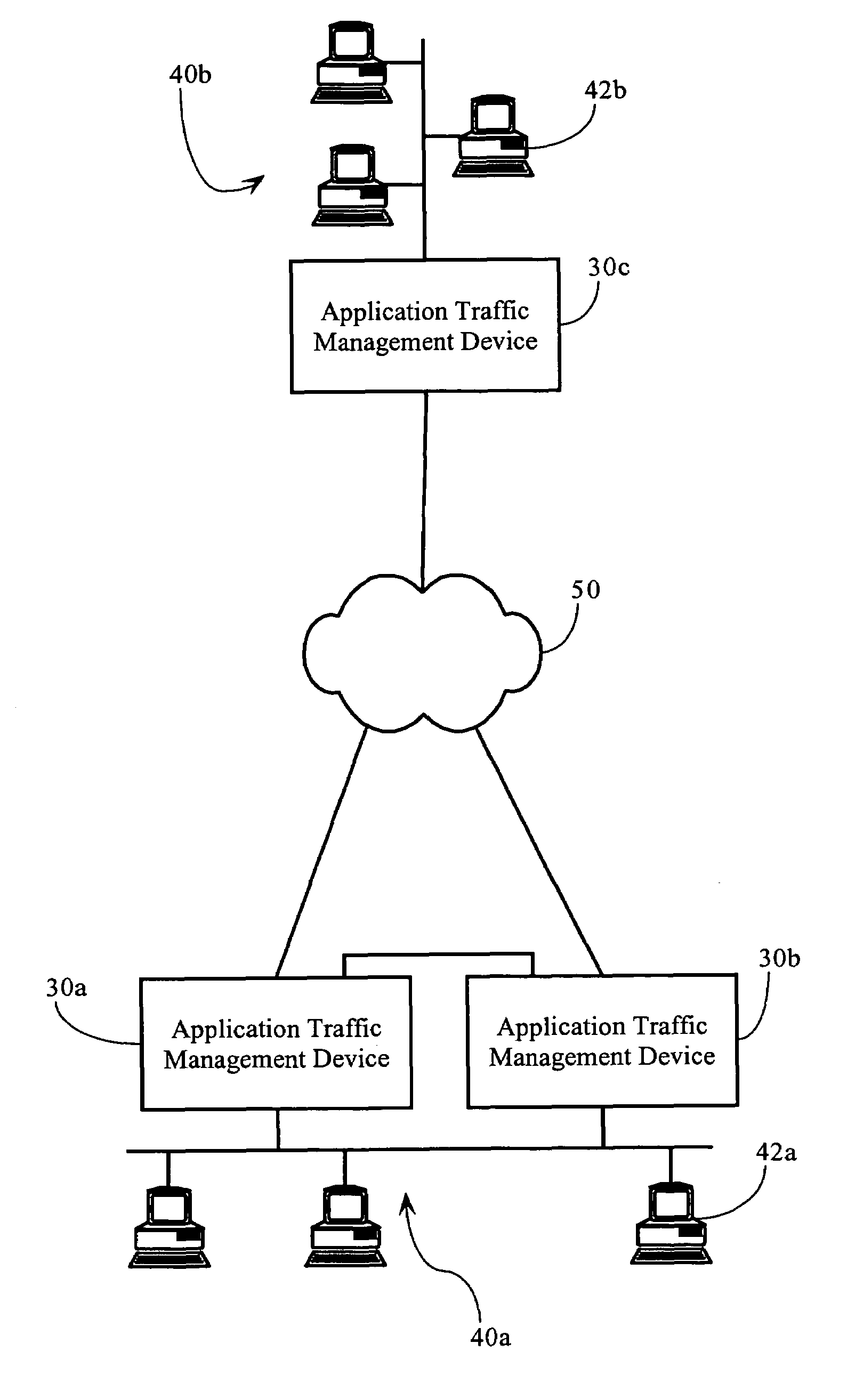
[0049]FIG. 2C illustrates the general operating environment in which implementations of the present invention may operate. As FIG. 2C illustrates, network 50 interconnects networks 40a and 40b. As FIG. 2A shows, computer network 40a interconnects several TCP / IP end systems, including client devices 42 and server device 44, and provides access to resources operably connected to computer network 50 via router 22. Access link 21 is a physical and / or logical connection between two networks, such as computer network 50 and network 40a. The computer network environment, including computer networks 40a, 40b, and 50 is a packet-based communications environment, employing TCP / IP protocols, and / or other suitable protocols, and has a plurality of interconnected digital packet transmission stations or routing nodes. Application traffic management devices 30a, 30b, and 30c are disposed on the communications path between end systems (e.g., end system 42b) connected to network 40b and end systems...


PUM


Abstract

Synchronization of network traffic compression mechanisms deployed in redundant network topologies. In one implementation, the present invention features the synchronization of compression statistics on redundant network devices to facilitate failover and load sharing operations in the management of data flows traversing computer network environments. In one implementation, compression meta data is appended to synchronization packets and transmitted to one or more partner or redundant network devices. The receiving network devices use the compression meta data to synchronize one or more data flow control processes or data structures. Implementations of the present invention also feature process flows that increase the efficiency of synchronizing compression related operations.

Description

CROSS-REFERENCE TO RELATED APPLICATIONS AND PATENTS[0001]The present application is a continuation-in-part of U.S. application Ser. No. 10 / 611,573 filed Jun. 30, 2003 and entitled “Network Traffic Synchronization Mechanism.” This application also makes reference to the following commonly owned U.S. patent applications and patents, which are incorporated herein by reference in their entirety for all purposes:[0002]U.S. patent application Ser. No. 08 / 762,828 now U.S. Pat. No. 5,802,106 in the name of Robert L. Packer, entitled “Method for Rapid Data Rate Detection in a Packet Communication Environment Without Data Rate Supervision;”[0003]U.S. patent application Ser. No. 08 / 970,693 now U.S. Pat. No. 6,018,516, in the name of Robert L. Packer, entitled “Method for Minimizing Unneeded Retransmission of Packets in a Packet Communication Environment Supporting a Plurality of Data Link Rates;”[0004]U.S. patent application Ser. No. 08 / 742,994 now U.S. Pat. No. 6,038,216, in the name of Rober...

Claims


Application Information

Patent Timeline
IPC IPC(8): G01R31/08G06F15/173H04J3/18H04L12/26H04L12/28
CPCH04L45/586H04L45/00H04L41/0896H04L41/0893H04L41/0895H04L41/0894
Inventor VARIER, ROOPESH R.STABILE, JAMES J.ARCHARD, PAUL LESLIERIDDLE, GUYJACOBSON, DAVID
Owner CA TECH INC
Why Eureka
Try Eureka