Ballistic protection shelter

a technology for protecting structures and buildings, applied in protective equipment, transportation and packaging, weapons, etc., can solve the problems of little protection for occupants of such structures from detonation and subsequent shrapnel

Inactive Publication Date: 2009-10-13
UNITED STATES OF AMERICA THE AS REPRESENTED BY THE SEC OF THE ARMY
View PDF11 Cites 60 Cited by
  • Summary
  • Abstract
  • Description
  • Claims
  • Application Information

AI Technical Summary

Benefits of technology

[0011]The above and other features of the invention, including various novel details of construction and combinations of parts, will now be more particularly described with reference to the accompanying drawings and pointed out in the claims. It will be understood that th

Problems solved by technology

In a hostile environment, the occupants of such structures have

Method used


Image

  • Ballistic protection shelter
  • Ballistic protection shelter
  • Ballistic protection shelter

Examples


Embodiment Construction

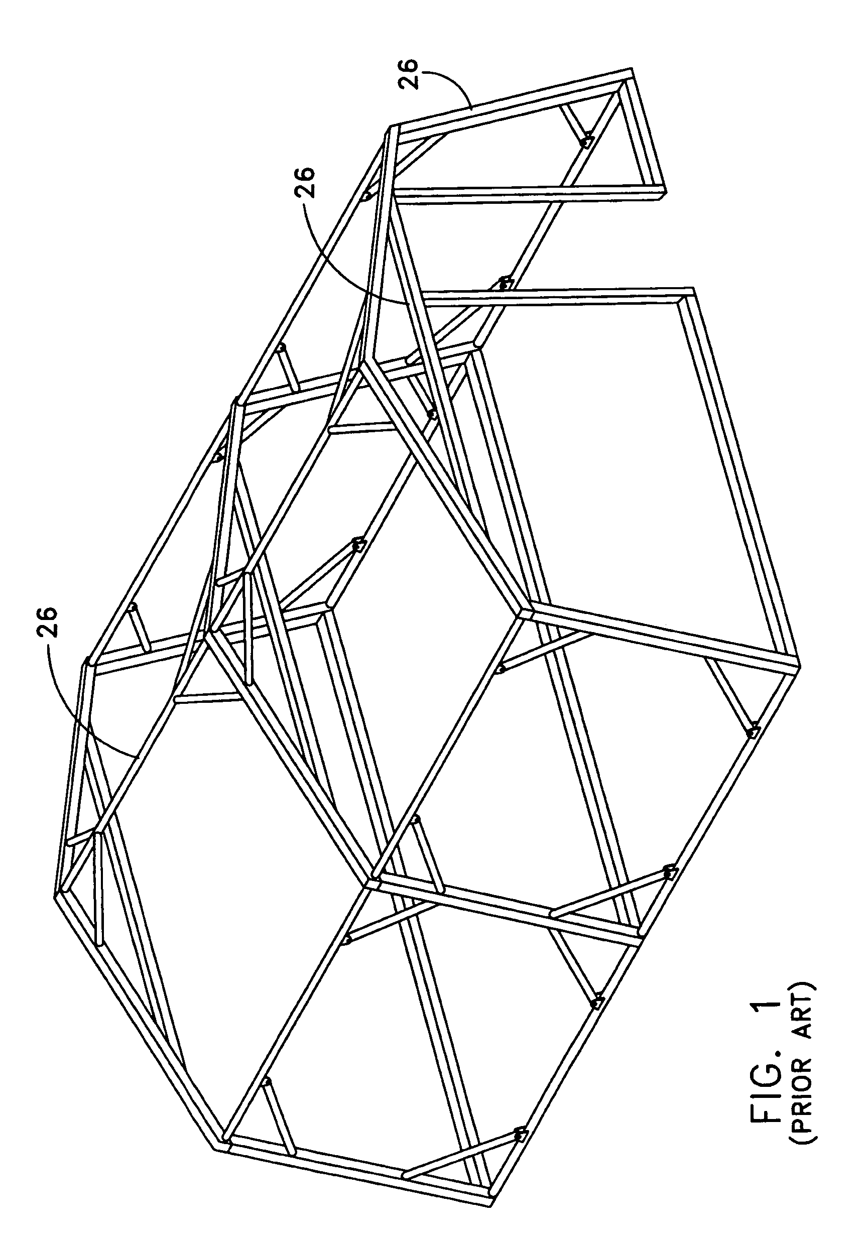
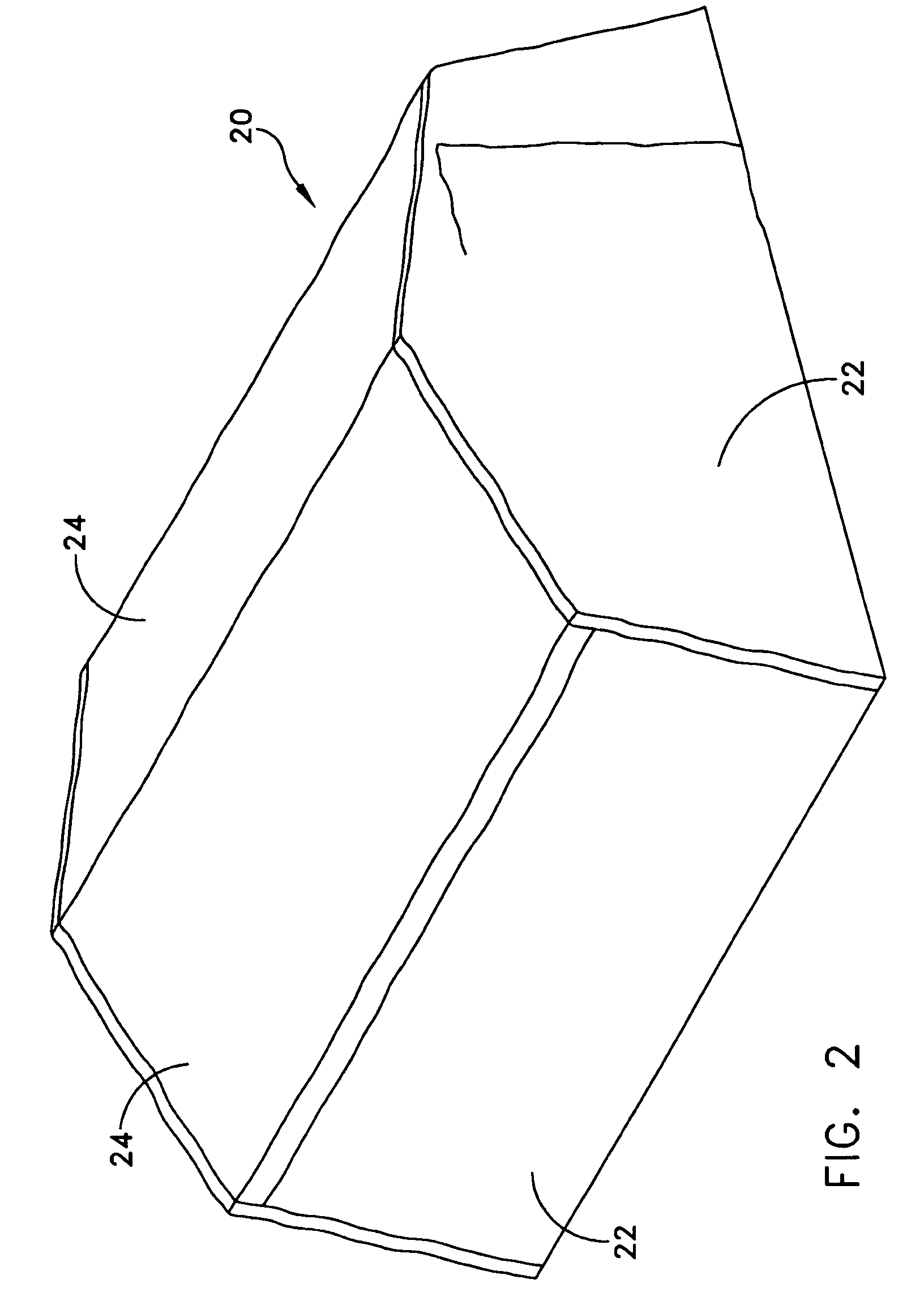
[0019]Referring to FIG. 2, it will be seen that the illustrative ballistic protection shelter includes a soft-walled shelter structure, or tent, 20 having soft wall portions 22 and soft roof portions 24, supported by rigid poles or frame assembly 26 (FIG. 1).

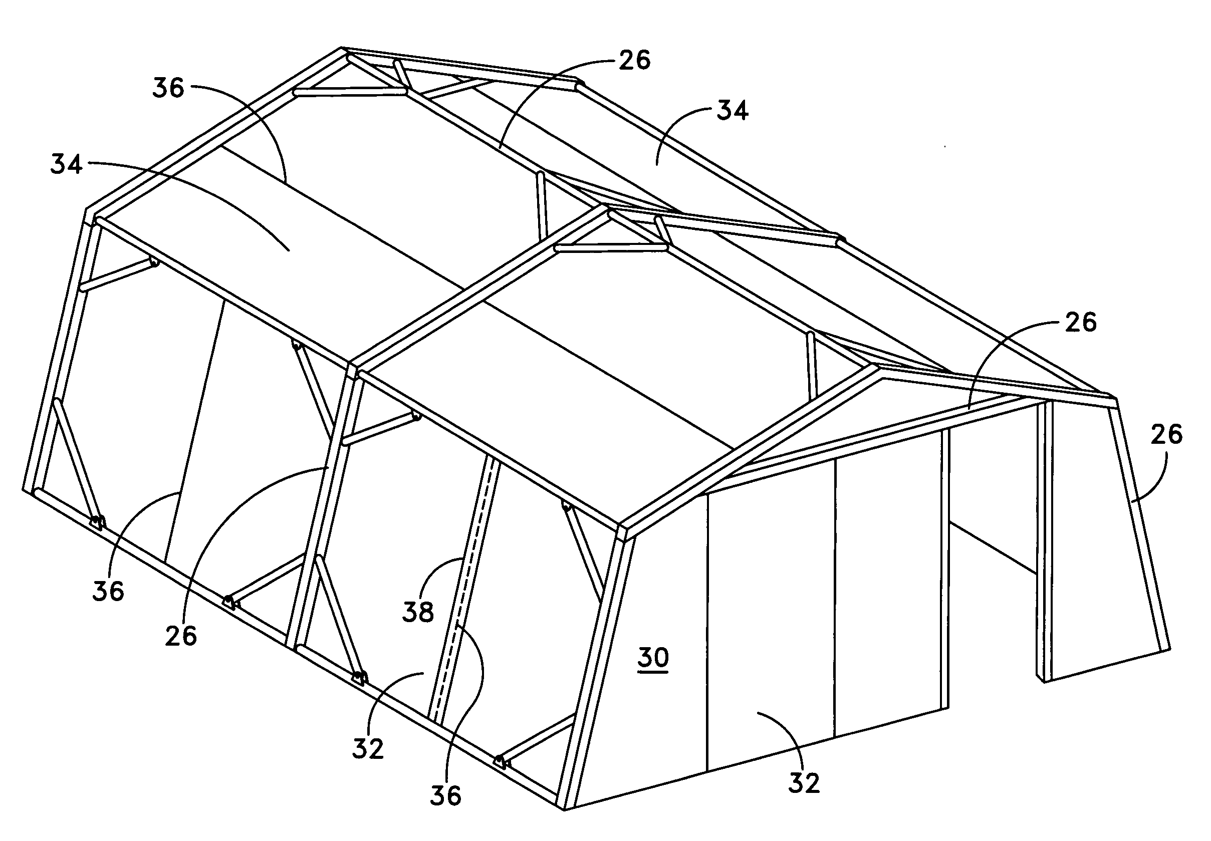
[0020]The illustrative shelter further includes an internal shelter structure 30 (FIG. 3) including at least rigid side wall panels 32 and, preferably, rigid roof panels 34. The rigid panels 32, 34 are interconnectable, and / or connectable to the frame assembly 26 (FIG. 5), for quick erection within the soft-walled structure 20. The rigid frame assembly 26 may support the soft wall portions 22 and the rigid side panels 32, or the rigid side panels 32 may stand by virtue of their own rigidity and interconnection.

[0021]The rigid panels 32, 34 may be interlocking with each seam 36 being covered by a lap 38 (a sample of such lapped seam being shown in FIG. 5) so that the lapped seams maintain the integrity of the protective shielding...


PUM


Abstract

A ballistic protection shelter includes a soft-walled shelter structure wherein soft wall and soft roof portions are supported on at least one rigid support member, and an internal shelter structure for disposition within the soft-walled shelter structure. The internal shelter structure includes at least rigid side wall panels connectable to each other to form an enclosure. The panels are of a ballistic protective material adapted to provide protection to shelter occupants against explosive detonations and shrapnel.

Description

STATEMENT OF GOVERNMENT INTEREST[0001]The invention described herein may be manufactured and used by the U.S. Government for governmental purposes without the payment of any royalty thereon.BACKGROUND OF THE INVENTION[0002]1. Field of the Invention[0003]The invention relates to structures for human habitation and is directed more particularly to tent-like structures for use in the field, as by soldiers.[0004]2. Description of the Prior Art[0005]Soldiers in the field are typically housed in soft-walled structures, such as tents. Such structures usually include soft wall portions and soft roof portions connected together and supported by a pole, or a series of poles and / or frame members.[0006]In a hostile environment, the occupants of such structures have little protection against detonations and consequent shrapnel. To improve protection under such conditions, high-value targets may be surrounded with concrete barriers and / or sand bags. Such external measures, however, readily identi...

Claims


Application Information

Patent Timeline
IPC IPC(8): B62D63/04E04B1/00E04B1/12E04H15/00E04H15/18
CPCE04H9/10E04H15/008F42D5/045F41H5/24E04H15/18
Inventor KOSTKA, FRANK
Owner UNITED STATES OF AMERICA THE AS REPRESENTED BY THE SEC OF THE ARMY
Why Eureka
Try Eureka