Screen and image projection system

a projection system and image technology, applied in the field of screen and image projection system, can solve problems such as difficult storage, and achieve the effect of improving projection image quality and keeping the projection surface smooth

Inactive Publication Date: 2009-10-13
YAMAUCHI NAOFUMI
View PDF4 Cites 14 Cited by
  • Summary
  • Abstract
  • Description
  • Claims
  • Application Information

AI Technical Summary

Benefits of technology

[0006]A screen of the present invention has two types of screen of differing optical characteristics formed on the same side of the same sheet, constructed capable of being wound in a single storage tube. Also, spring support bodies having spring characteristics that allow winding like an elastic spring are coupled on both side ends parallel to the winding direction of the screen. With type of structure, side ends of the screen long in the winding direction do not get caught inside, allowing the surface of the screen surface to be a smooth projection surface, and it is possible to improve projection image quality.
[0007]Further, it is possible to use a screen that is bent from a boundary of screens having differing characteristics. In this way, it becomes possible to project an image in a state where the size of a screen surface used is made constant. Also, by providing a spindle having an operation of drawing the screen downwards at a bent section, it becomes possible to keep the projection surface smooth even when the screen is bent. Also, this spindle has a slit structure constructed gripping the front and rear surfaces of the screen, and it becomes possible to freely pass the screen through an inner part of this slit.
[0008]Further, by having a structure where spring support bodies having spring properties are divided at the boundary of the screens having differing characteristics, a smooth projection surface is made possible as far as the vicinity of the bent section.

Problems solved by technology

However, with the screen disclosed in patent publication 1 that is capable of switching between screen surfaces of differing characteristics, one of the screen surfaces is exposed, and there is a problem that storage is difficult.
Also, if these two types of screen surfaces are stored at the same time, there is a problem that it is necessary to individually provide a storage tube for each screen surface.

Method used


Image

  • Screen and image projection system
  • Screen and image projection system
  • Screen and image projection system

Examples


embodiment 1

[Embodiment 1]

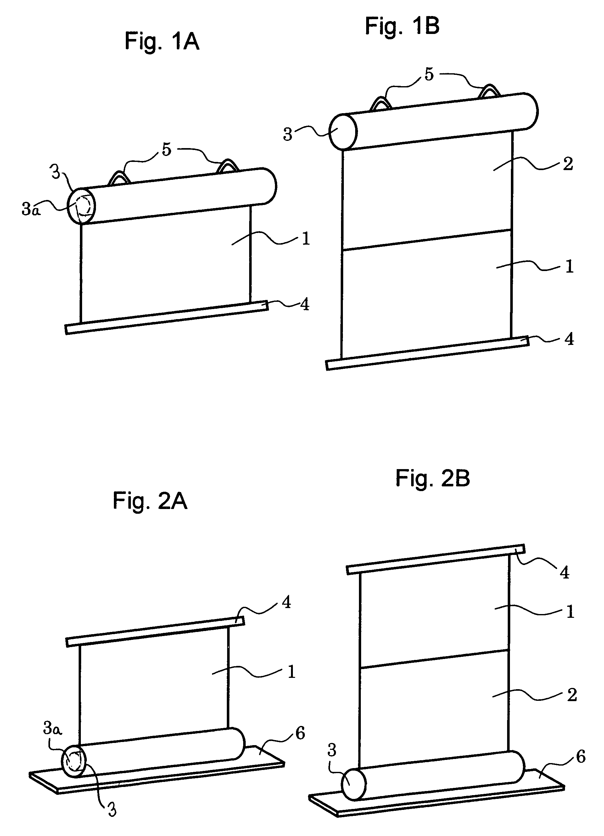
[0024]The structure of the screen of this embodiment is shown in FIG. 1. FIG. 1A shows a state where only a first screen having first optical characteristics is withdrawn or drawn out from a storage tube, and FIG. 1B shows a state where the first screen and a second screen having second characteristics are withdrawn or drawn out from the storage tube. As shown in FIG. 1B, the first screen 1 having first optical characteristics and the second screen having second optical characteristics have projection surfaces provided continuously facing in the same direction. An end bearing frame 4 is attached to a drawing out side end section (lower side) of the first screen 1, and the end bearing frame 4 functions as a spindle for successively pulling out drawn out sections of the first screen 1 and the second screen 2 in the direction of gravity. Since the turning force of the screen in the lateral direction is regulated by the end bearing frame 4, it is possible project an image ...

embodiment 2

[Embodiment 2]

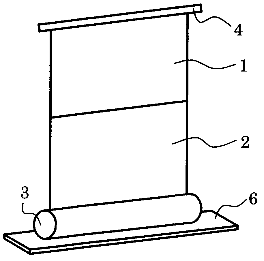
[0029]The structure of the screen of this embodiment is shown in FIG. 2. FIG. 2A shows a state where only a first screen 1 having first optical characteristics is drawn out from a storage tube, and FIG. 2B shows a state where the first screen and the second screen 2 having second characteristics are drawn out from the storage tube. The point of difference between this embodiment and the embodiment shown in FIG. 1 is that the storage tube 3 is arranged on the floor, and the screen surfaces are pulled up to an upper section. Elements that have the same operation as the first embodiment are assigned the same reference numerals, and description thereof is omitted. With this embodiment, since the storage tube 3 is floor mounted, a support base 6 for preventing falling is attached to the storage tube 3 so that the screen does not fall when the screen surface is pulled out. This support base 6 can also have any structure as long as it is a structure that prevents the screen f...

embodiment 3

[Embodiment 3]

[0036]A cross section of the screen of this embodiment is shown schematically in FIG. 5. With the structure shown in FIG. 1 and FIG. 2, when the second screen is used the height of the screen is twice that of a normal screen, and so there may be a disadvantage in use that the height of projection to the second screen is increased. With this embodiment, in order to avoid this drawback, in the case of using the second screen a structure is adopted where the first screen 1 is folded back to the rear surface of the second screen 2.

[0037]The screen of this embodiment has a columnar spindle body in the form of a cylindrical spindle 19 and a spindle frame 20 joined by a clamp frame 21. This spindle has a slit structure. That is, a screen surface passes through a slit shaped gap formed by the cylindrical spindle 19, the spindle frame 20 and the clamp frame 21. The cylindrical spindle 19 and the spindle frame 20 are formed from a fluorine series high polymer material such as Te...


PUM


Abstract

A screen having two optical characteristics is realized in a compact structure. As a result, a structure is provided where two types of screen surface having different optical characteristics are formed on the same side of the same sheet, and wound in a single storage tube, and it is possible to pull out and fix the first screen from the storage tube in a state where the second screen is stored in the storage tube.

Description

BACKGROUND OF THE INVENTION[0001]The present invention relates to a screen for a projector for projecting an optical image from a high luminance CRT or liquid crystal projector etc., and to a projection system comprising these components.[0002]A projection system for displaying an image by projecting an optical image using a high luminance CRT or liquid crystal projector can simply display a high definition image on a large screen, which means that it has become widely used as an information communication tool for a large number of users. In a screen for this projector, there have been schemes to improve light use efficiency by having a structure where a white material having high optical reflectance and a light reflecting film are coated on a surface, and to improve visibility for a plurality of observers by dispersing beads on the surface to cause light diffusion. Also, a screen that is capable of switching between screen surfaces of differing characteristics, such as a surface th...

Claims


Application Information

Patent Timeline
Patent Type & Authority Patents(United States)
IPC IPC(8): G03B21/56G03B21/60G03B21/58
CPCG03B21/56
Inventor YAMAUCHI, NAOFUMI
Owner YAMAUCHI NAOFUMI
Why Eureka
Try Eureka