Optical pickup

a pickup and optical technology, applied in the field of optical pickups, can solve the problems of preventing accurate writing or reading, affecting the accuracy of the magnet boundary position, and the position of the magnetic pole boundary may not be uniformly positioned with respect to the outer shape of the magnet, so as to achieve the effect of suppressing the generation of angular moment that would tilt the objective lens, improving the accuracy of the magnet boundary position, and increasing the drive force produced by each coil

Inactive Publication Date: 2009-10-13
HITACHI MEDIA ELECTORONICS CO LTD
View PDF2 Cites 0 Cited by
  • Summary
  • Abstract
  • Description
  • Claims
  • Application Information

AI Technical Summary

Benefits of technology

[0008]When a magnet magnetized with N poles and S poles alternately as disclosed in Patent Document 1 is used, it is important that the boundaries of the magnetic poles are located at predetermined reference positions. If the boundaries of the magnetic poles are displaced from the reference positions, the magnetic flux density distribution with respect to the focusing coils or the tracking coils would vary, and, as a result, the distribution of driving force generated in the focusing coils or the tracking coils would become asymmetrical with respect to the center of each coil. Such asymmetrical driving force distribution with respect to the center of each coil would generate angular moment(torque), which would cause the objective lens to be inclined. If the objective lens is inclined, the focusing spot will be blurred due to optical aberrations, thereby possibly preventing accurate writing or reading.
[0011]It is therefore an object of the invention to provide an optical pickup of the type in which different magnetic poles are adjacently disposed, wherein the accuracy of magnet boundary positions is improved, the angular moment generated through the coils is reduced, and the inclination of the objective lens is minimized.
[0016]In accordance with the invention, in an optical pickup configured such that a plurality of magnets are disposed adjacent to one another, the accuracy of the magnet boundary positions can be improved even when there is dimensional error in any of the magnets. As a result, the magnetic flux density distribution can be maintained symmetrical, and the generation of angular moment that would tilt the objective lens can be suppressed. Thus, information can be read or written on an optical disc accurately.
[0017]Furthermore, because the distance between each magnet and each coil can be made uniform, the drive force produced by each of the coils can be increased, so that the writing or reading of information on the optical disc can be performed at high speeds.

Problems solved by technology

If the objective lens is inclined, the focusing spot will be blurred due to optical aberrations, thereby possibly preventing accurate writing or reading.
Given manufacturing errors, however, the magnetic pole boundaries may not be necessarily positioned uniformly with respect to the outer shape of the magnet.
Thus, there is the problem that the magnetic pole boundary positions are displaced from reference positions.
In the optical pickup of Patent Document 1, the use of three magnets is also problematic in that the magnet boundaries may be displaced from their reference positions if there is a dimensional error in any of the magnets.

Method used


Image

  • Optical pickup
  • Optical pickup
  • Optical pickup

Examples


embodiment 1

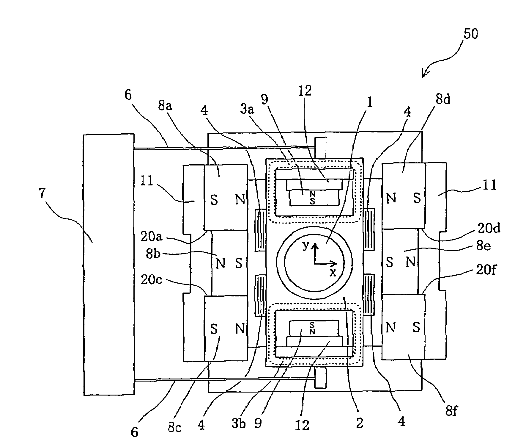
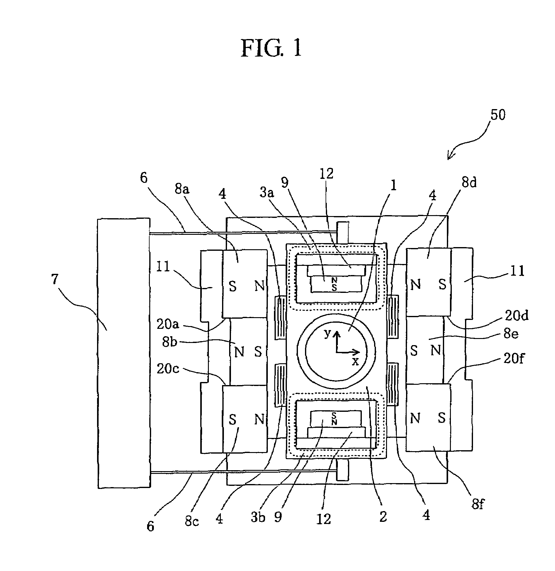
[0025]An embodiment of the optical pickup according to the invention will be described with reference to the drawings. Initially, an optical disc drive 100 in which an optical pickup 110 is mounted is described with reference to a block diagram of FIG. 7. The optical disc drive 100 includes a spindle motor 120 for rotating an optical disc 101, an optical pickup 110 for reading or writing information on the optical disc 101, and a controller 130 for controlling these components. The optical pickup 110 includes an objective lens driving means 50, of which the details will be described later, and optical components such as a laser light emitting device 111.

[0026]A disc rotation control circuit 131, which is connected to the controller 130, receives an instruction therefrom and drives the spindle motor 120 on which the optical disc 101 is mounted. A feed control circuit 132, which is also connected to the controller 130, receives an instruction therefrom and causes the optical pickup 11...


PUM


Abstract

In an objective lens driving means of an optical pickup, the accuracy of the boundary position of magnets is improved, the generation of angular moment through coils is suppressed, and the inclination of the objective lens is reduced. An optical pickup for reading or writing information on an optical disc using an objective lens includes a lens holder for holding an objective lens, three magnets disposed facing to each of the two sides of the lens holder that are parallel to the focusing direction and the tracking direction, and a yoke for mounting these magnets. The yoke includes a central yoke surface for mounting the central one of the three magnets, and outer yoke surfaces for mounting the outer two of the three magnets. A step is formed between the central yoke surface and each of the outer yoke surfaces.

Description

BACKGROUND OF THE INVENTION[0001]1. Field of the Invention[0002]The present invention relates to an optical pickup provided in optical disc drives for reading information recorded on a recording surface of an optical disc or for recording information thereon.[0003]2. Background Art[0004]Conventional objective lens driving means provided in the optical pickup of an optical disc drive is composed of a moving part on which an objective lens is mounted, support members for supporting the moving part, focusing coils, tracking coils, a yoke, and magnets.[0005]When a drive current is applied to the focusing coils, electromagnetic force is produced by the interaction of the current with the magnetic flux produced by the magnets. The electromagnetic force drives the moving part in a focusing direction, which is either toward or away from the optical disc surface. Similarly, when a drive current is applied to the tracking coils, electromagnetic force is produced by the interaction of the curr...

Claims


Application Information

Patent Timeline
Patent Type & Authority Patents(United States)
IPC IPC(8): G02B7/02
CPCG02B7/02
Inventor KIMURA, KATSUHIKOSENGA, JUNICHI
Owner HITACHI MEDIA ELECTORONICS CO LTD
Why Eureka
Try Eureka