Check patentability & draft patents in minutes with Patsnap Eureka AI!

Method for flow control in a communication system

a communication system and flow control technology, applied in the field of wireless access networks, can solve problems such as potential underflow, and achieve the effects of reducing the frequency of sending flow control messages, saving bandwidth, and saving bandwidth on the backhaul portion of the network

Active Publication Date: 2009-10-13
ALCATEL-LUCENT USA INC
View PDF21 Cites 11 Cited by
  • Summary
  • Abstract
  • Description
  • Claims
  • Application Information

AI Technical Summary

Benefits of technology

[0009]According to the method of the present invention, the counter threshold is dynamically established based on the status (occupancy or availability) of the transmission buffer. In one exemplary embodiment, when the transmission buffer is relatively full, a lower count threshold is set. The low count threshold will cause flow control messages to be sent more frequently. Because the transmission buffer is relatively full, a flow control message will notify the second communication device that the first communication device can only accommodate a limited amount of data. The potential therefore exists for underflow—either because not enough data is sent over a period of time until the next flow control message and / or because a large amount of data is transmitted before the next flow control message. By increasing the frequency of sending the flow control messages, the method according to the present invention keeps the data flow coming without starving the transmission link at the first communication device. When the transmission buffer is relatively empty, a higher count threshold is set to reduce the frequency of sending flow control messages. Because the flow control message will indicate that the second communication device can send a relatively large amount of data, flow control messages do not need to be sent as frequently. In a communication system, this saves bandwidth on the transmission link between the two communication devices. Specifically to a wireless communication system, this saves bandwidth on the backhaul portion of the network. It also reduces the CPU processing power requirement on both devices.

Problems solved by technology

The potential therefore exists for underflow—either because not enough data is sent over a period of time until the next flow control message and / or because a large amount of data is transmitted before the next flow control message.

Method used


Image

  • Method for flow control in a communication system
  • Method for flow control in a communication system
  • Method for flow control in a communication system

Examples


Embodiment Construction

[0014]The present invention provides a method of controlling the flow of data from one communication device to another in a network. For the purpose of explanation only, the method of the present invention will be described as applied to the wireless access network illustrated in FIG. 1, wherein the data communicated is communicated in packets. However, it will be readily understood that the invention is not limited to this implementation or form of data transmission.

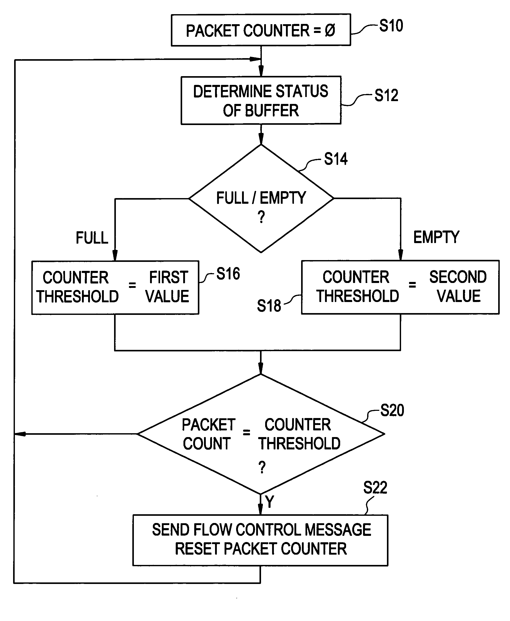
[0015]In one exemplary embodiment, the flow control method according to present invention regulates the flow of packets from the BSC 110 to the BTS 120 using a flow control message sent from the BTS 120 to the BSC 110. The flow control message informs the BSC 110 of the number of packets that the BTS 120 can accommodate. Using this information and, typically, the number of packets it already sent to the BTS 120, the BSC 110 determines the additional number of packets to be sent to the BTS 120. In the embodiments of the ...


PUM


Abstract

In the method of flow control, a flow control message, requesting more data, is sent from a first communication device based on an amount of data output by the first communication device and an available data storage capacity of the first communication device.

Description

BACKGROUND OF THE INVENTION[0001]A communication system, particularly a wireless access network, contains various components and units to provide voice and data services over the air interface. As shown in FIG. 1, the wireless access network typically includes an access terminal 130, a communication transmission device such as a Base Station Transmission System (“BTS”) 120, and a communication system control device such as a Base Station Controller (“BSC”) 110. The BSC 110 receives data from the core network 100 and passes the data to the BTS 120 so that the BTS 120 can transmit the data to an access terminal (“AT”) 130 over a wireless link 125. Data is communicated in the reverse direction as well and passed from the AT 130 to the core network 100. The connection between the BTS 120 and BSC 110 is usually considered as the backhaul portion of the network and is typically through a T1 facility 115.[0002]Data frames transmitted from the BSC 110 to the BTS 120 are buffered at the BTS ...

Claims


Application Information

Patent Timeline
IPC IPC(8): G06F15/16H04B7/26H04L12/56
CPCH04L47/10H04L47/14H04L47/39H04W28/12H04L47/29H04W92/12H04W28/02G06F13/385H04W8/04
Inventor YANG, TOMASZHANG, QINQING
Owner ALCATEL-LUCENT USA INC
Features
  • R&D
  • Intellectual Property
  • Life Sciences
  • Materials
  • Tech Scout
  • Unparalleled Data Quality
  • Higher Quality Content
  • 60% Fewer Hallucinations
Learn More