Inspection apparatus for wire-processing machine

a wire-processing machine and inspection apparatus technology, applied in the direction of electronic circuit testing, contact member manufacturing, other manufacturing equipment/tools, etc., can solve the problem of not being able to integrate in an automated wire-processing process, at least without great effor

Inactive Publication Date: 2009-10-20
KOMAX HOLDING
View PDF32 Cites 15 Cited by
  • Summary
  • Abstract
  • Description
  • Claims
  • Application Information

AI Technical Summary

Benefits of technology

[0004]The present invention solves the task of avoiding the disadvantages of the known facilities and creates a wire-processing apparatus the makes inspecting an electrical wire end connection within an automated wire-processing procedure feasible.
[0007]The main advantages achieved by the present invention are that already existing modules of the wire-processing facility can be used to inspect the wire end connection produced in the automated wire-processing operation. For an automated wire-processing operation, grippers arranged at swivel arms for example or grippers arranged at transfer facilities are used to feed the wire to the processing stations. The gripper is not only moved in a circle, or in the transfer direction, but also linearly in the swiveling arm longitudinal axis, or crosswise to the transfer direction. The linear movement going horizontally into the depth of the wire-processing facility or the crosswise movement of the gripper is necessary for supplying wires to different crimp contacts, feeding wires with grommets or supplying wires to relegated processing stations, for example. For the wire-processing facility per the present invention, the linear movement of the gripper is not only used for feeding the wire to the processing stations, but also for the automated inspection of the wire end connection. The wire end connection is fed to a holder and is held by it. The gripper grasps the wire, or rather firmly holds the wire and loads the wire with a pull out force in the longitudinal axis of the wire by means of a linear movement away from the holder. With the multiple use or the linear movement of the gripper used for different purposes, the wire-processing facility can be set up more easily and operated more productively with better quality assurance.

Problems solved by technology

The disadvantage of the known inspection facilities is that they cannot be integrated in an automated wire-processing process, at least without great effort.

Method used


Image

  • Inspection apparatus for wire-processing machine
  • Inspection apparatus for wire-processing machine
  • Inspection apparatus for wire-processing machine

Examples


Embodiment Construction

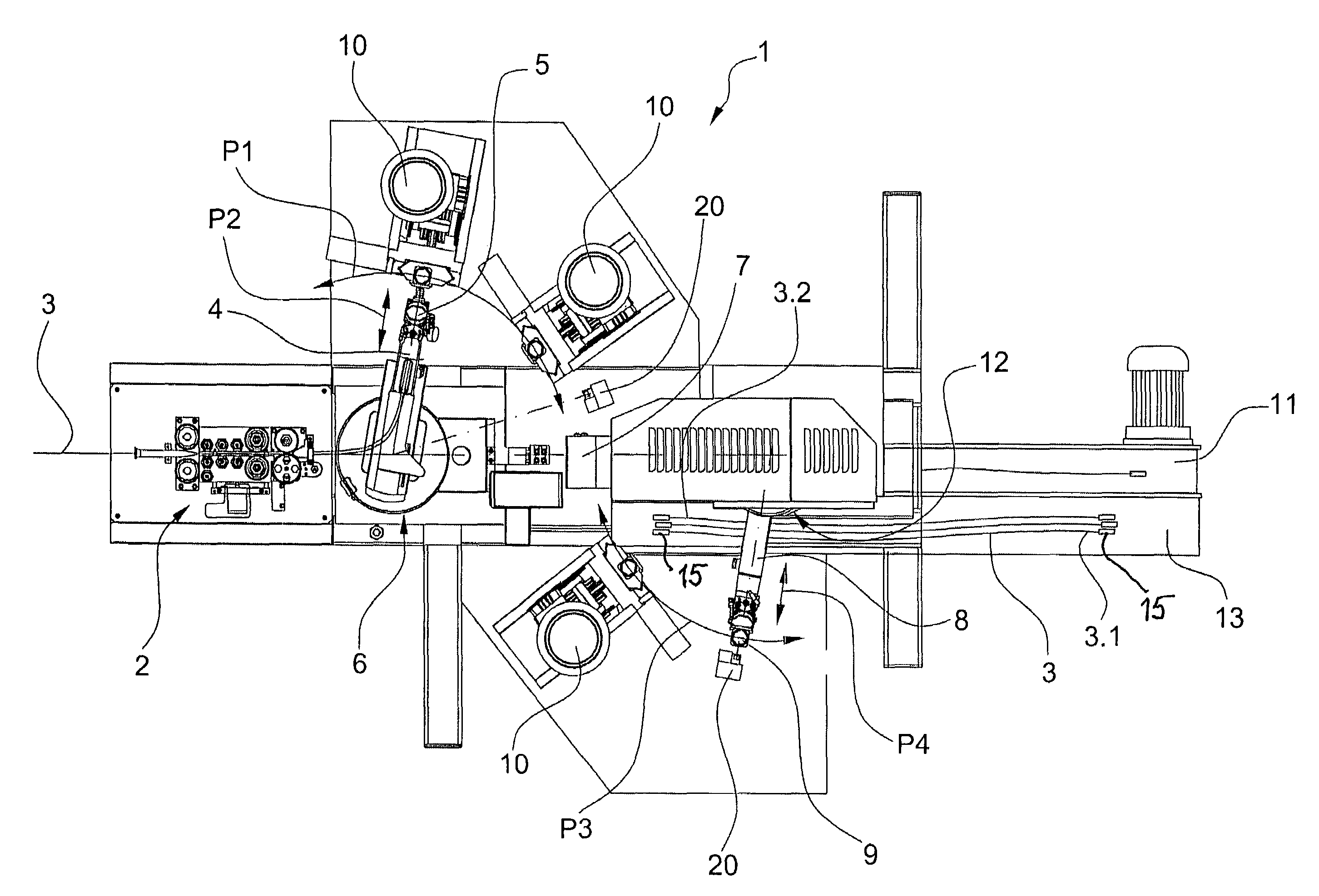
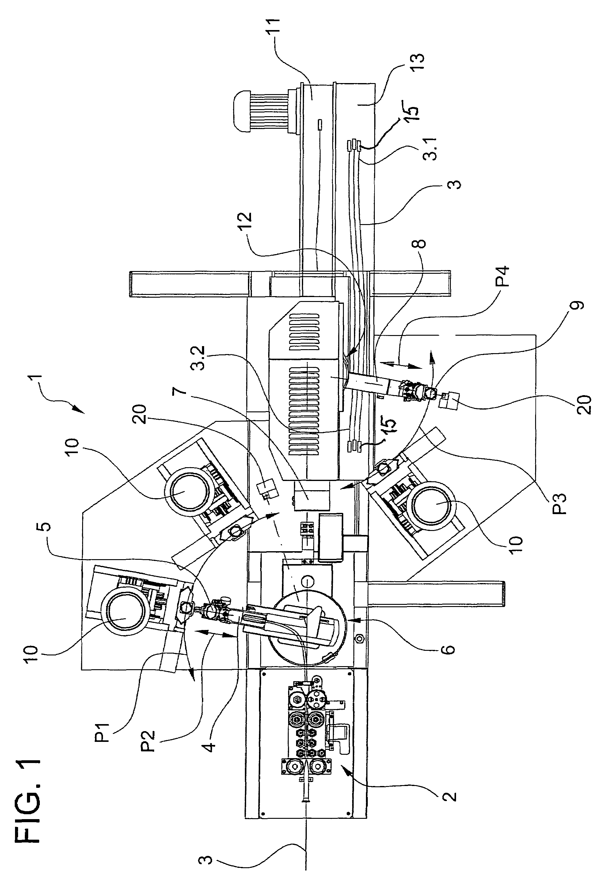
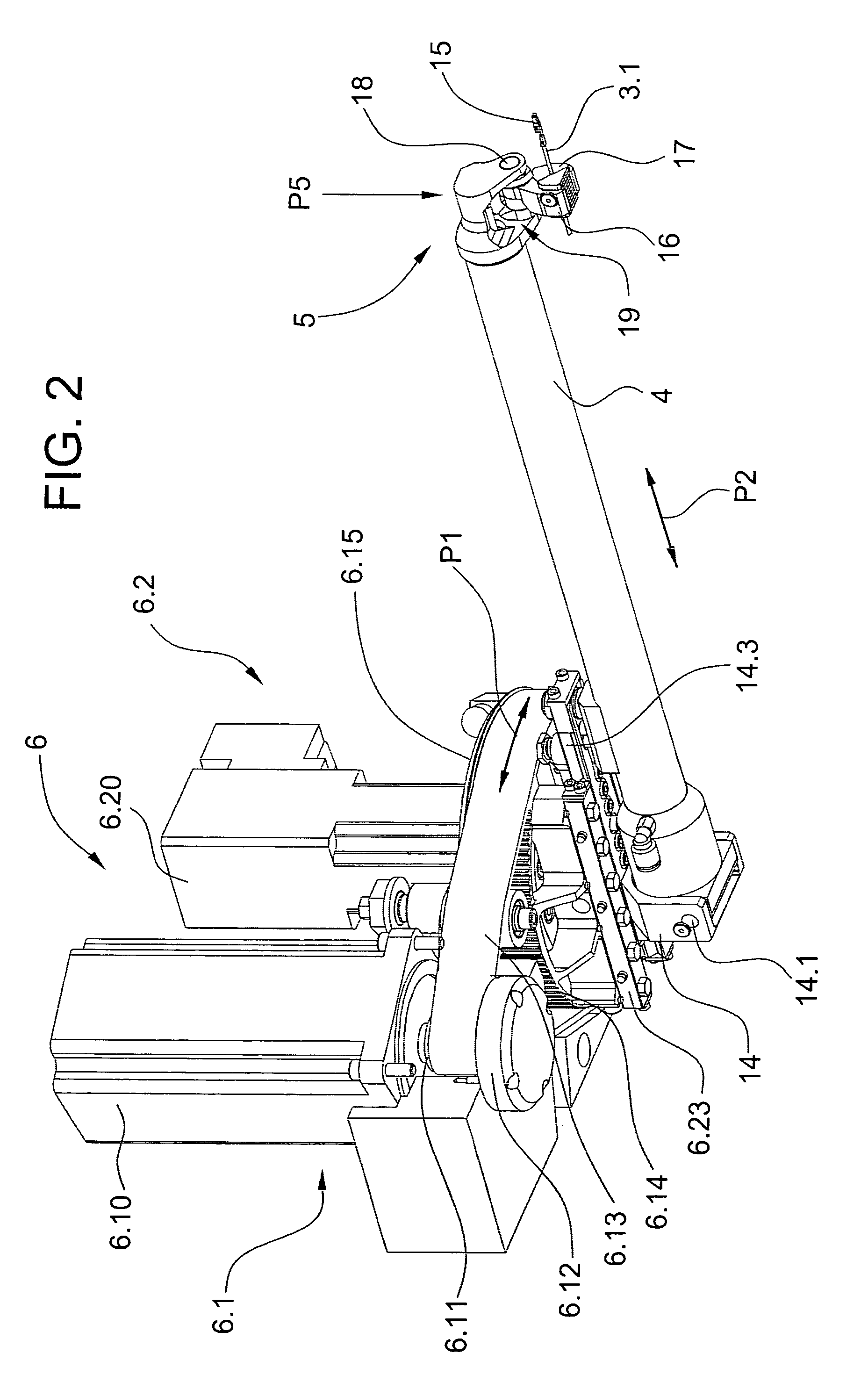
[0015]FIG. 1 shows a wire-processing machine 1 with a wire advance means provided as a belt drive 2, wherein the belt drive 2 feeds a wire 3 to a first swivel arm 4 with a first gripper 5. Through a first drive means 6, the first swivel arm 4 can be operated in a swinging movement symbolized with an arrow P1 and / or a linear movement symbolized with an arrow P2. The wire 3 can be separated and stripped with knives 7.

[0016]Furthermore, the wire-processing apparatus 1 includes a second swivel arm 8 with a second gripper 9. Through a second drive means 12, the second swivel arm 8 can be operated in a swinging movement symbolized with an arrow P3, and / or a linear movement symbolized with an arrow P4. The first swivel arm 4 serves as a furnishing facility by means of the turning movement P1 and the linear movement P2 at processing stations 10 arranged at the opposite sides of the longitudinal axis of the wire 3 (for example, crimp presses and / or grommet assembly) for leading end 3.1. The ...


PUM

PropertyMeasurementUnit
pull out forceaaaaaaaaaa
movementaaaaaaaaaa
forceaaaaaaaaaa

Abstract

A wire-processing apparatus has grippers feeding a wire to processing stations for producing wire end connections. A holder is used to inspect the wire end connection, wherein the linear movement of the grippers is used for the automated inspection of the wire end connection by applying a pull out force along a longitudinal axis of the wire while the holder is retaining the connection.

Description

BACKGROUND OF THE INVENTION[0001]The present invention concerns an inspection apparatus and a procedure for a wire-processing machine with processing stations for electrical wire outfitting, where at least one gripper as a furnishing unit feeds the wire to the processing station.[0002]Known facilities for inspecting a crimp connection consist of a holder for holding the crimp contact and of a pulling device for loading the wire connected to the crimp contact by way of a stripping crimp and a conductor crimp with a force in the direction of the longitudinal axis of the cable. The inspection facilities can be operated manually or by motor, where the measured holding force is displayed by means of force sensors. If the crimp connection does not or only partially withstands a predetermined pull out force, the wire is manually discarded.[0003]The disadvantage of the known inspection facilities is that they cannot be integrated in an automated wire-processing process, at least without gre...

Claims


Application Information

Patent Timeline
Patent Type & Authority Patents(United States)
IPC IPC(8): B23P19/00H01R43/048H01R43/052H01R43/28
CPCH01R43/0488H01R43/052Y10T29/49204H01R43/28Y10T29/53213Y10T29/53235Y10T29/532Y10T29/49117Y10T29/5151Y10T29/53217Y10T29/49004Y10T29/5193Y10T29/5149Y10T29/5313Y10T29/49174
Inventor VIVIROLI, STEFAN
Owner KOMAX HOLDING
Why Eureka
Try Eureka