Secure coin-operated machine

a coin-operated machine and coin-operated technology, applied in the field of coin-operated machines, can solve problems such as the attraction of fraudulent users to coin-operated machines

Inactive Publication Date: 2009-10-20
PARKEON +1
View PDF17 Cites 25 Cited by
  • Summary
  • Abstract
  • Description
  • Claims
  • Application Information

AI Technical Summary

Benefits of technology

[0016]Another characteristic of the coin-operated machine according to the invention is that the control means that trigger the displacement of the trap to the closing position are formed by a finger carried by the lower part of the coin receiving system opposite the chute channel, which finger is adapted to penetrate into the channel when the said lower part of the receiving system is in place in its compartment, so as to prevent the movement of the trap to the closing position.

Problems solved by technology

It is well known that coin-operated machines attract fraudulent users, who try their best to get to the cash.

Method used


Image

  • Secure coin-operated machine
  • Secure coin-operated machine
  • Secure coin-operated machine

Examples


Embodiment Construction

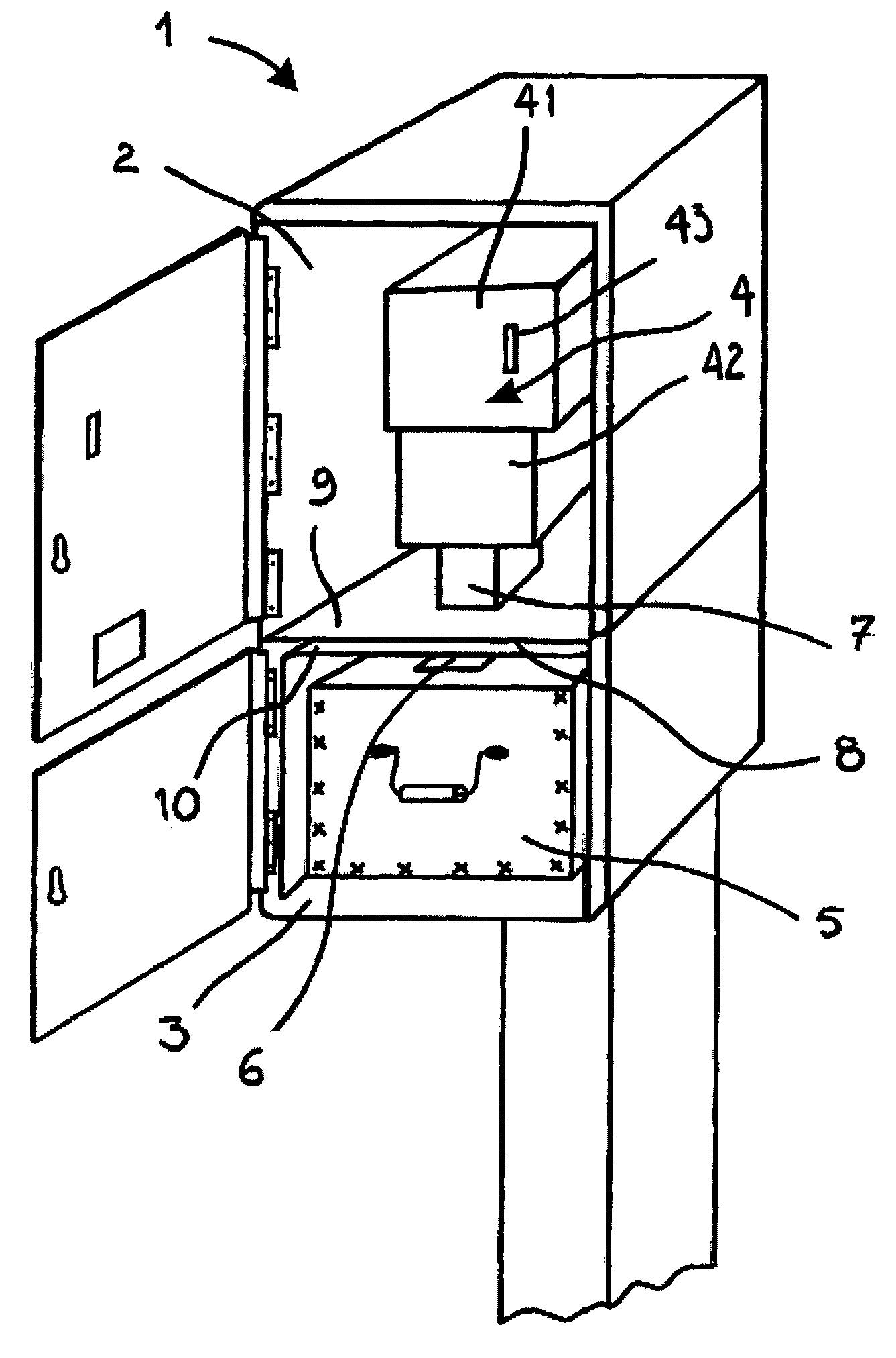
[0024]FIG. 1 shows a coin-operated machine that is generally designed to supply a product or service in exchange for the payment of a corresponding amount of money, which payment is made with coins. Such a device can for instance be a public telephone, a beverage dispenser or a ticket vending machine.

[0025]In the description below, the machine (reference 1) is a Pay & Display machine designed for the payment of parking spaces.

[0026]Pay & Display machine 1 contains two distinct compartments, 2 and 3 respectively, arranged one above the other. According to the example of the embodiment represented in FIG. 1, each compartment is accessible by means of a corresponding access door closed by an appropriate lock.

[0027]Upper compartment 2 includes all the mechanisms required for the Pay & Display machine to operate. The different means themselves are known and do not call for a more detailed description. compartment 2 also includes the coin receiving device 4.

[0028]The coin receiving device...


PUM


Abstract

The invention concerns a service and / or product dispensing apparatus comprising a coin-receiving device, a coin-storage box (5) and said chute (7) transferring coins from the receiving device to the box (5). The invention is characterised in that said chute (7) co-operates with a closing device (8) comprising a trap (82) mobile between a position closing and a position opening said chute (7), said device (8) co-operating with control means (40) adapted to trigger the displacement of the trap (82) into its closing position when at least part of the coin-receiving device (4) is being dismantled.

Description

FIELD OF THE INVENTION[0001]This invention concerns coin-operated machines used to dispense products or services such as Pay & Display parking machines or pay telephones. This invention is particularly aimed at protecting the coins stored in such machines from theft.BACKGROUD OF THE INVENTION[0002]In general, coin-operated machines comprise a receiving mechanism that enables the issuing of a service or product in return for the payment of the corresponding amount in coins. Such mechanisms contain the entire path of the coins, which are chiefly moved by gravity from the inlet formed by the coin insertion slot and the two outlets placed below the said inlet, namely a bowl for returning unused or unsuitable coins and a box for the received coins. Between the inlet and outlet are placed means to authenticate the coins inserted and escrow means designed for storing valid coins temporarily.[0003]In general, such machines include two distinct compartments closed by distinct doors, where th...

Claims


Application Information

Patent Timeline
Patent Type & Authority Patents(United States)
IPC IPC(8): G07F1/00G07D11/00G07F1/04G07F9/06G07F9/10
CPCG07D11/0009G07F9/10G07F9/06G07F1/04Y10S193/01G07D11/125
Inventor RICHARD, THIERRYESCALIER, JEAN
Owner PARKEON
Why Eureka
Try Eureka