
Knee airbag

a knee airbag and driver technology, applied in the direction of vehicle components, pedestrian/occupant safety arrangements, vehicular safety arrangments, etc., can solve the problems of inability to maintain the space between the steering column and the occupant's knee, the construction is relatively complicated and therefore expensive, and the effect of improving protection

Inactive Publication Date: 2009-10-20
FORD GLOBAL TECH LLC
View PDF11 Cites 39 Cited by
  • Summary
  • Abstract
  • Description
  • Claims
  • Application Information

AI Technical Summary

Benefits of technology

[0007]The invention has the object of developing an airbag of the type mentioned at the beginning to the effect that it deploys better and provides better protection for a vehicle occupant, in particular the driver, in the event of a crash.
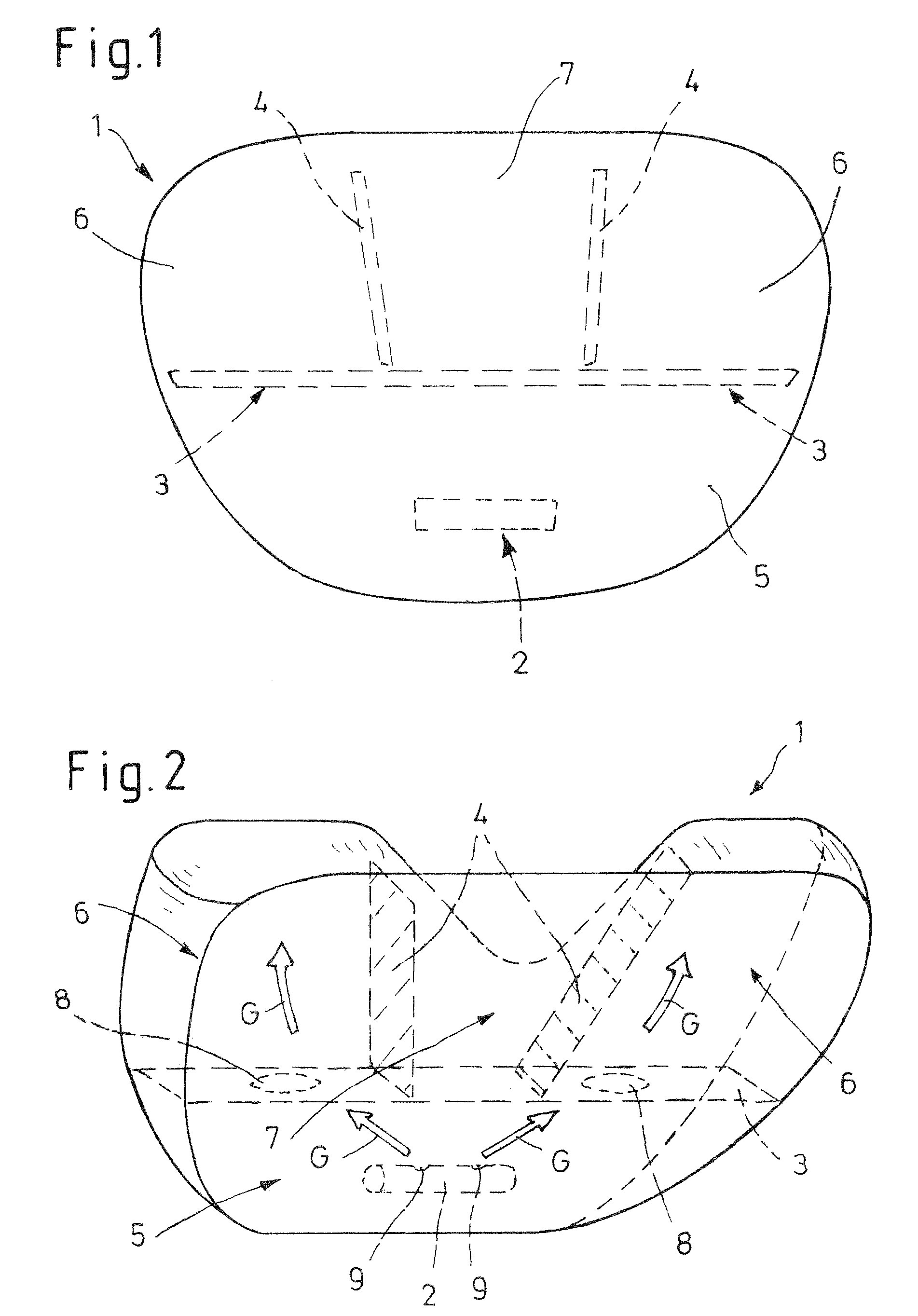
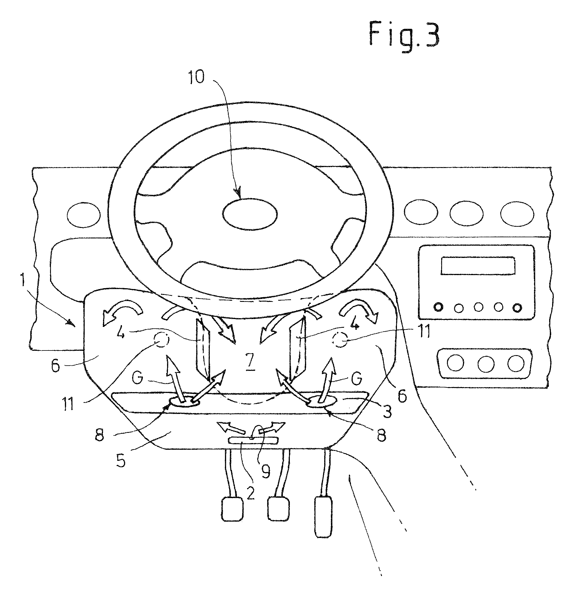
[0009]Owing to the fact that the airbag comprises a first catch strap dividing the airbag essentially horizontally, and two catch straps extending essentially vertically from the first catch strap, it is possible to rapidly fill the space between the steering column and the knees of the driver by the airbag in the event of a crash. In addition, the shape of the inflated airbag can therefore be matched better to the steering column and its surroundings, which results in greater protection for the driver. Furthermore, in a departure from the prior art, the inflation sequence of the airbag can change in such a manner that it first of all deploys in the lateral direction and subsequently inflates in the direction of the steering wheel, so that the knees of the driver are already protected at a particularly early time.
[0011]The first catch strap is preferably provided in such a manner that a first pressure chamber extending essentially horizontally over the width of the airbag is formed, and the two catch straps extending essentially vertically from the first catch strap are provided in such a manner that two outer pressure chambers and a central pressure chamber are formed, and that a gas outlet opening of the gas generator is arranged in the first pressure chamber. With a preferred embodiment of this type, the airbag can be particularly readily molded around the steering column and at the same time a smaller volume which is to be inflated can be set, so that correspondingly small gas generators can be used.
[0014]In order to achieve a rapid deployment of the airbag in the outer pressure chambers too, the first catch strap can have gas passage openings which preferably connect the first pressure chamber in each case to the outer pressure chambers. A rapid propagation of the gas pressure is therefore achieved.

Problems solved by technology

However, this construction is relatively complicated and therefore expensive.
In addition, there is the problem that the space between the steering column and the occupant's knee changes continuously, for example depending on the selected position of the legs or knees with respect to the steering column.
This is not possible with the airbags from the prior art which only have catch straps running horizontally, since the latter, as seen over the width, have an approximately constant thickness.

Method used


Image

  • Knee airbag
  • Knee airbag
  • Knee airbag

Examples


Embodiment Construction

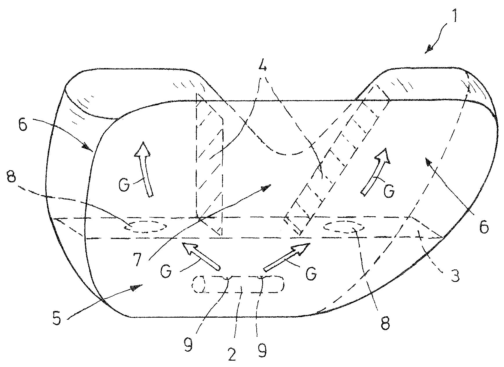
[0024]The figures show a driver's knee airbag, which is referred to as a whole by 1, for a motor vehicle, with a gas generator 2, a plurality of chambers 5, 6, 7 and catch straps 3, 4.

[0025]The airbag 1 comprises an envelope which defines a bag interior. For purposes of description only, the envelope may be said to comprise left and right lateral walls, and a top wall. The lateral and top walls are not necessarily separate pieces, nor are they necessarily flat, nor are there necessarily distinct boundaries between the walls, as they may blend gradually into one another. A first catch strap 3 extends laterally across the interior of the airbag to divide it essentially horizontally. The lateral ends of the first catch strap 3 may contact and / or be sealed with the left and right lateral walls of the envelope . Alternatively, the lateral ends of the first catch straps may be spaced from the left and right lateral walls to leave gaps. Two catch straps 4 have lower ends adjacent the upper...


PUM


Abstract

The invention relates to a driver's knee airbag (1), in particular for a motor vehicle, with a gas generator (2), a plurality of chambers (5, 6, 7) and catch straps (3, 4). So that it deploys better and provides better protection for a vehicle occupant, in particular the driver, in the event of a crash, it comprises a first catch strap (3) dividing the airbag essentially horizontally, and two catch straps (4) extending essentially vertically from the first catch strap (3). The space between the steering column and the knees of the driver is therefore rapidly filled by the airbag in the event of a crash.

Description

BACKGROUND[0001]1. Technical Field[0002]The invention relates to a driver's knee airbag, in particular for a motor vehicle, with a gas generator, a plurality of chambers and catch straps.[0003]2. Background Art[0004]The airbags known in general from the prior art are intended to protect the vehicle occupants against injuries in the event of an impact. It is therefore important that the airbags deploy rapidly and provide optimum protection. Over the course of progressive development of safety devices in the motor vehicle, in an ever greater number of vehicles use is made of what is referred to as a knee airbag which, in addition to the improved restraint function of the particular occupant, also protects the latter, in particular the driver, from contact with the lower structures, such as the steering column. For this purpose, it is necessary to develop special airbags tailored to these requirements.[0005]DE 199 00 592 A1 describes a knee-supporting device, in which a covering is arr...

Claims


Application Information

Patent Timeline
Patent Type & Authority Patents(United States)
IPC IPC(8): B60R21/20B60R21/203B60R21/205B60R21/233B60R21/231
CPCB60R21/206B60R21/231B60R21/233B60R2021/23324B60R2021/23169
Inventor HEITPLATZ, FRANKVARCUS, JOHANNES A.
Owner FORD GLOBAL TECH LLC
Learn More