Rotor shaft of a spinning rotor

a technology of rotating rotor and rotating shaft, which is applied in the direction of rod connection, magnetic circuit rotating parts, magnetic circuit shape/form/construction, etc., can solve the problems of insubstantial wear of the contact cover mechanical stress of the supporting disc, power loss, etc., and achieve the effect of producing economically and reliably

Inactive Publication Date: 2009-10-20
OERLIKON TEXTILE GMBH & CO KG
View PDF11 Cites 8 Cited by
  • Summary
  • Abstract
  • Description
  • Claims
  • Application Information

AI Technical Summary

Benefits of technology

[0011]Proceeding from the aforementioned prior art, the invention is based on the object of providing a rotor shaft of a spinning rotor with annular magnetic bearing components arranged so as to be rotationally engaged, which are configured such that these magnetic bearing components can be produced economically and reliably with respect to function.
[0014]The invention has the advantage, in particular, that owing to the use of slotted permanent magnet rings, a limited deformability of these permanent magnet rings is achieved and this facilitates, on the one hand, the slipping of these components onto associated receivers, and also their secure locking on the receivers by drawing on corresponding ring liners. In other words, in a configuration of this type of the permanent magnet rings, it is ensured that the permanent magnet rings are not damaged during their positioning on the bearing lug of their receiver nor during their locking by a ring liner.
[0016]It is provided in this case, in a refined embodiment, that the slotted permanent magnet ring, prior to its installation, has an internal diameter, which is slightly above the external diameter of the associated bearing lug of the receiver. The sliding fit thus produced facilitates the slipping of the permanent magnet ring onto its bearing seat and therefore provides the prerequisite that damage to the slotted permanent magnet ring is very substantially ruled out during this action. As the external diameter of the slotted permanent magnet ring is also slightly above the internal diameter of the ring liner guaranteeing tensile strength, which is to be fixed on the permanent magnet ring, it is nevertheless ensured that the slotted permanent magnet rings, after drawing on the ring liners, are locked so as to be rotationally engaged and very substantially so as to be speed-resistant on the bearing lug of the receiver.
[0019]In an advantageous embodiment, the ring liners are made of a material guaranteeing high tensile strength, preferably carbon fiber reinforced plastics material. Such CFRP ring liners, on the one hand, guarantee tensile strength substantially better than comparable steel liners and are also significantly lighter, which, owing to the low flywheel effect, for example, has a positive effect on the acceleration capacity of the single motor rotor drive.

Problems solved by technology

Even if these support disc bearing arrangements have been successful in practice, they have the disadvantage that the support discs are mechanically substantially stressed, in particular in the region of their contact surfaces.
The milling work occurring in these regions leads not only to not insubstantial wear of the contact coverings of the support discs, but also to power losses.
This type of fixing of the permanent magnets rotating at a high speed was not satisfactory; there has now been a change to drawing the annular permanent magnets of the rotor onto bearing lugs of special receivers and securing the drawn-on permanent magnets with an external ring liner against the centrifugal forces occurring during the spinning operation.
In the two methods, the diameter of the connection faces had to have very exacting tolerances, as there was otherwise the risk of damage to the relatively sensitive ring magnets during the pressing-on processes.
The described methods proved to be not very effective overall, as despite exacting tolerances, damage to ring magnets during pressing on could not always be avoided.

Method used


Image

  • Rotor shaft of a spinning rotor
  • Rotor shaft of a spinning rotor
  • Rotor shaft of a spinning rotor

Examples


Embodiment Construction

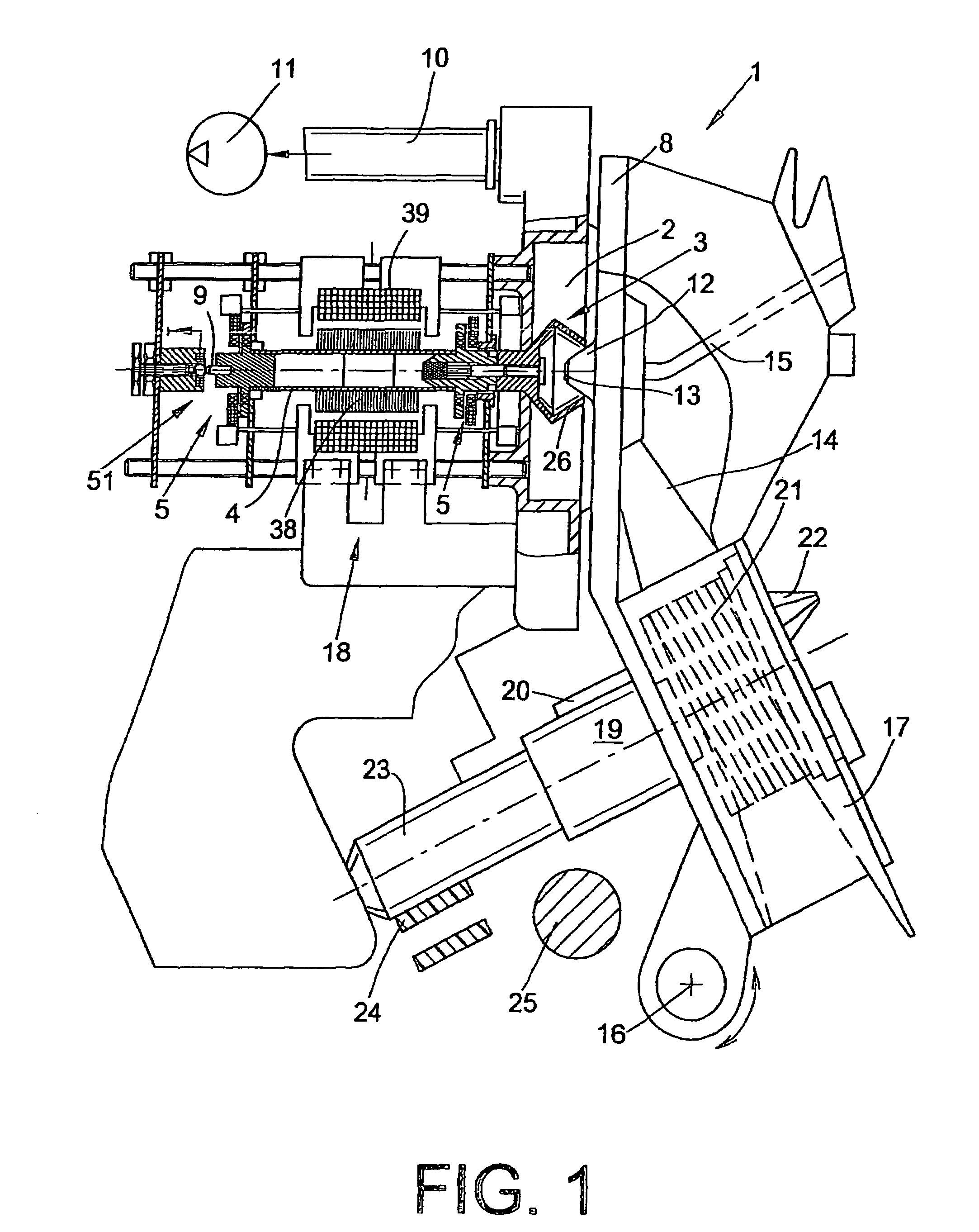
[0025]An open end spinning device of an open end rotor spinning machine is shown in FIG. 1 and designated by the reference numeral 1. Open end spinning devices I of this type, which are known per se, in each case have a rotor housing 2, in which the spinning cup 26 of a spinning rotor 3 circulates at a high speed. The spinning rotor 3 is driven in this case by an electric motor single drive 18, and is supported by its rotor shaft 4 in magnetic bearing arrangements 5, the permanent magnetic bearing components of which support the rotor shaft 4 both radially and axially.

[0026]In the embodiment shown, apart from the magnetic bearing arrangements 5, a rear position sensor 51 is also provided. The structure and the function of bearing sensors 51 of this type are prior art and described in detail, for example in German Patent Publication DE 100 22 736 A1.

[0027]As known, the rotor housing 2 which is open per se toward the front, is closed during operation by a pivotable cover element 8 and...


PUM

PropertyMeasurementUnit
internal diameteraaaaaaaaaa
external diameteraaaaaaaaaa
tensile strengthaaaaaaaaaa

Abstract

A rotor shaft of a spinning rotor has an annular magnet bearing component which is secured from the centrifugal force effective during the spinning process by means of a ring liner, for radially and axially supporting the rotor shaft, whereby the rotatable magnetic bearing component interacts with a stationary magnetic bearing component. The magnetic bearing component linked with the rotor shaft (4) of the spinning rotor (3) is configured as a slotted permanent magnet ring (32,42), thereby ensuring the deformability required for fitting a ring liner (6,7).

Description

CROSS-REFERENCES TO RELATED APPLICATIONS[0001]This application claims the benefit of German patent application 102004005846.6, filed Feb. 6, 2004, herein incorporated by reference.BACKGROUND OF THE INVENTION[0002]The invention relates to a rotor shaft of a spinning rotor and, more particularly, to a spinning rotor shaft with an annular magnetic bearing component, secured with respect to the centrifugal force effective during the spinning process by a ring liner, for radially and axially supporting the rotor shaft, and wherein the rotatable magnetic bearing component interacts with a stationarily arranged magnetic bearing component.[0003]In conjunction with open end rotor spinning machines, spinning rotors and their bearing are known in various embodiments and described in detail in the patent literature. Spinning rotors of this type, as is known, run at a high speed during the spinning process in a rotor housing which is acted upon by reduced pressure. The majority of open end spinn...

Claims


Application Information

Patent Timeline
Patent Type & Authority Patents(United States)
IPC IPC(8): H02K1/27H02K1/28H02K15/03H02K7/09D01H4/14F16C39/06
CPCD01H4/14F16C35/00F16C32/047F16C32/0478F16C32/0468Y10T403/7098F16C2340/18
Inventor BUHREN, STEPHAN
Owner OERLIKON TEXTILE GMBH & CO KG
Why Eureka
Try Eureka