Profile clamp

a technology of profile clamping and clamping rod, which is applied in the direction of vehicle/pulley rope, mechanical apparatus, couplings, etc., can solve the problems of low stability of steel profile clamps at relatively high temperatures, loss of elasticity at high temperatures, and leakage of joints

Inactive Publication Date: 2003-01-09
ABB (SCHWEIZ) AG +1
View PDF3 Cites 9 Cited by
  • Summary
  • Abstract
  • Description
  • Claims
  • Application Information

AI Technical Summary

Problems solved by technology

These steel profile clamps are not stable at relatively high temperatures.
Alternatively, they have too high of a coefficient of thermal expansion 18.times.10.sup.-6 to 22.times.10.sup.-6 m / mK (for austenitic, creep-resistant steels), which causes loss of elasticity at high temperatures and, thus, leakages in the joint.
Thus, the known profile clamps, which are made of ferritic or pure austenitic steel, are not suited to join the housing or other components of turbo chargers because the joint would leak at temperatures up to 750.degree. C. due to the excessively high coefficients of thermal expansion of the conventional clamp material.
Leaking joints will, among other things, lead to a substantial loss of output from the turbochargers.
In addition, a leaking or loosening connection constitutes a security risk, because turbochargers that have been assembled with these clamps could burst as a result of the loose connection, thereby increasing the risk of injury.

Method used


Image

  • Profile clamp
  • Profile clamp

Examples


Embodiment Construction

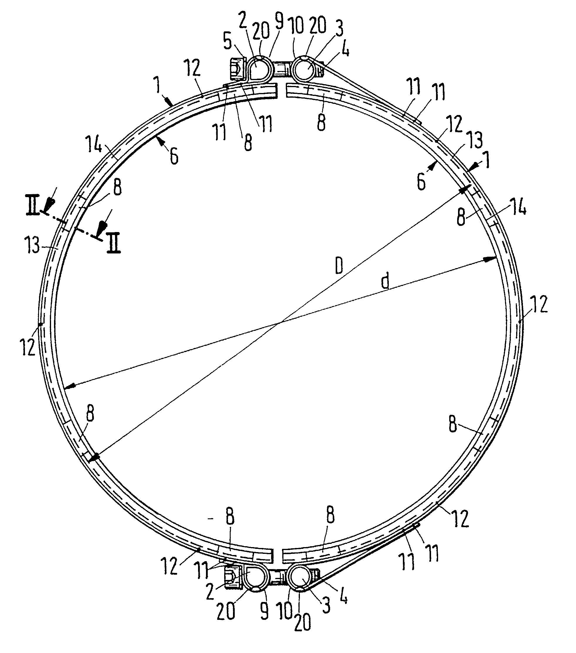
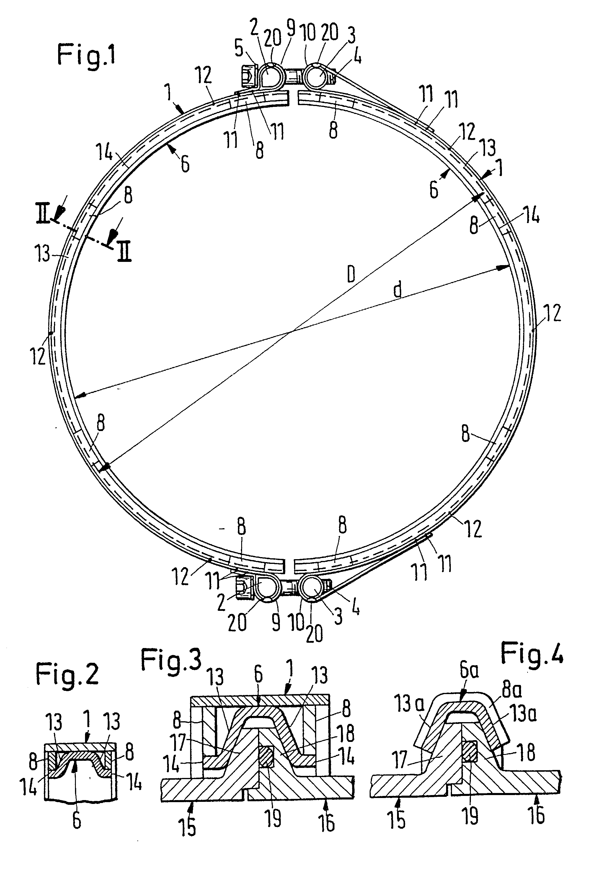
[0025] Referring now to FIGS. 1-3, a profile clamp according to the present invention is illustrated. The profile clamp includes two approximately semicircular clamping bands 1, four bolts 2, 3, two clamping bolts 4, two plain washers 5, two approximately semicircular ring segments 6 and a plurality of reinforcements, which are preferably in the form of sheet metal strips 8. Sheet metal strips 8 are distributed over the circumference of the clamp on both sides of the circular ring segments 6. Each clamping band 1 has end sections that are bent radially outwardly and back to form loops 9. The ends of the clamping band 1 are welded by, for example, projection welds 11, to the clamping band 1 to maintain the shape of the loops 9, 10. One bolt 2, 3 is placed within each loop 9, 10. Each loop 9, 10 has a slit extending around a major portion of the respective bolts 2, 3. One of the headed clamping bolts 4 has its shaft extend through the slits within the loops 9, 10. The shaft of bolt 4 ...


PUM

PropertyMeasurementUnit
temperatureaaaaaaaaaa
temperaturesaaaaaaaaaa

Abstract

A steel profile clamp is used to join flanged component parts. The profile clamp has at least partially conical side walls that are bent radially inwardly. The profile clamp has welding joints to maintain the shape of the clamp. The steel is martensitic for increased load-carrying capacity of the joint. The steel material, in an ambient temperature range of 20° C. to 750° C., has a coefficient of thermal expansion that is at least 0.3x10⁻⁶ m/mK lower than that of the coefficient of thermal expansion of a ferritic casting material. The method for manufacturing the profile clamp includes prequenching and tempering the material of the profile clamp when it is in the form of a strip. After forming and welding the profile clamp, the weld is subject to induction tempering.

Description

[0001] This is a continuation-in-part application of U.S. Ser. No. 10 / 141,509, filed on May 7, 2002, now pending which is a continuation of U.S. Ser. No.: 09 / 696,650, filed on Oct. 25, 2000, now U.S. Pat. No. 6,383,315, which is a divisional of U.S. Ser. No: 09 / 226,184, filed on Jan. 5, 1999, now abandoned.[0002] 1. Field of the Invention[0003] The present invention relates to a profile clamp and a method for manufacturing the profile clamp. More specifically, the present invention relates to a profile clamp, having conical side walls that are bent radially inwardly, for connecting components that have flanges at their respective ends.[0004] 2. Discussion of the Related Art[0005] Profile clamps, per s, are known, for example, from German Reference DE 30 38 491 C2, U.S. Pat. No. 3,498,649, U.S. Pat. No. 3,964,773, French Reference No. 1,016,629 and from the brochures "NORMA Conical Flange Joints", .COPYRGT. 1979 and 1988, "NORMA Profile Clamp with Conical Flange", .COPYRGT. November ...

Claims


Application Information

Patent Timeline
Patent Type & Authority Applications(United States)
IPC IPC(8): C22C38/44C22C38/46F16L23/08
CPCC22C38/44Y10T403/217F16L23/08C22C38/46
Inventor KREIPE, HANS-JURGENWEISHEIT, CLAUS DIETER
Owner ABB (SCHWEIZ) AG
Why Eureka
Try Eureka