
System and method for process monitoring

a technology of process monitoring and system, applied in the direction of electrical programme control, program control, nuclear elements, etc., can solve the problems of inability of automated systems to make an appropriate and complete response, and only take action based on specific data

Active Publication Date: 2009-10-20
AIR PROD & CHEM INC
View PDF129 Cites 66 Cited by
  • Summary
  • Abstract
  • Description
  • Claims
  • Application Information

AI Technical Summary

Problems solved by technology

However, these automated systems can only take action based on the specific data available to them and specific pre-defined thresholds.
When undesirable conditions result due to interactions among components and / or conditions within the process plant, or unexpected fault conditions occur, an automated system typically is unable to make an appropriate and complete response.

Method used


Image

  • System and method for process monitoring
  • System and method for process monitoring
  • System and method for process monitoring

Examples


Embodiment Construction

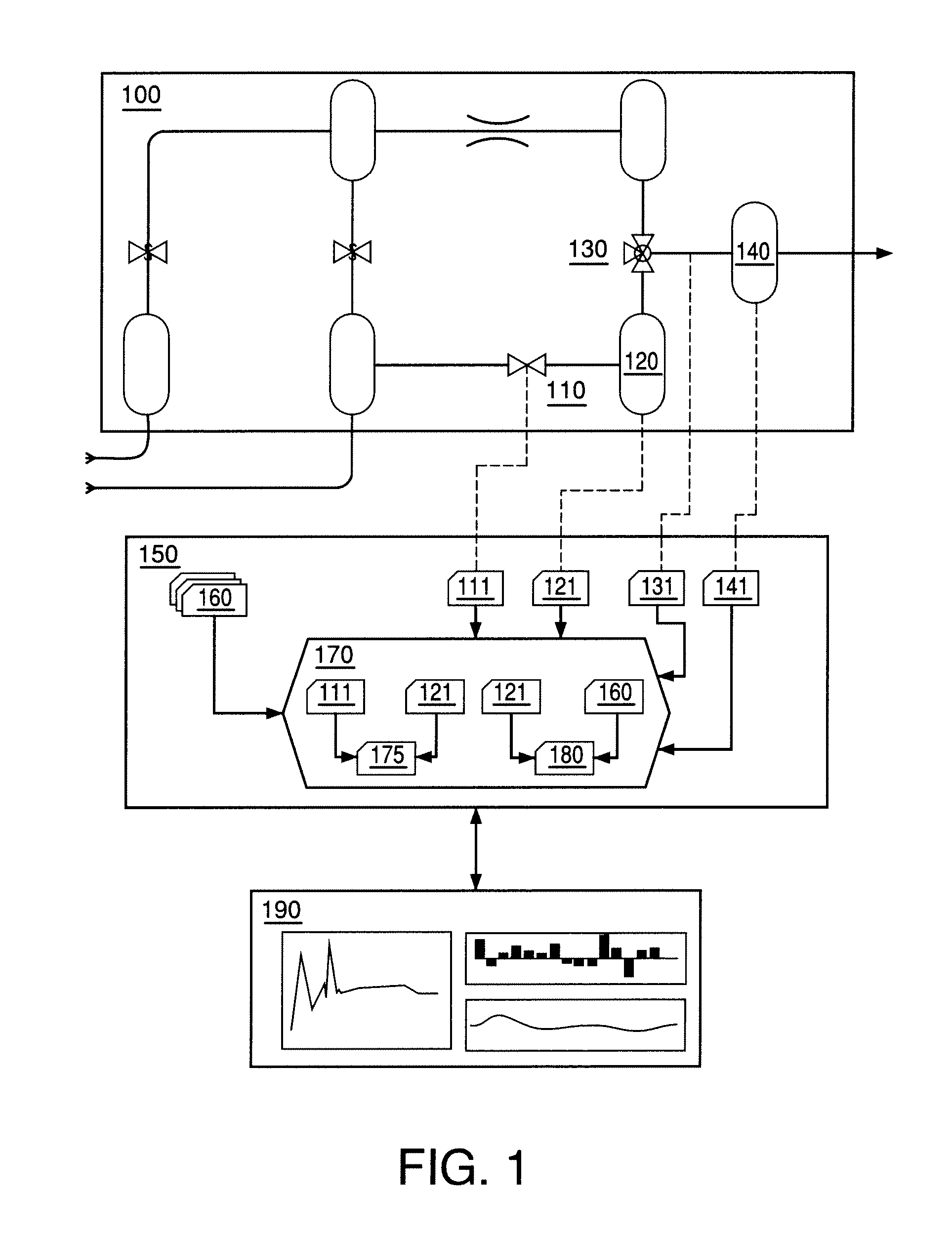
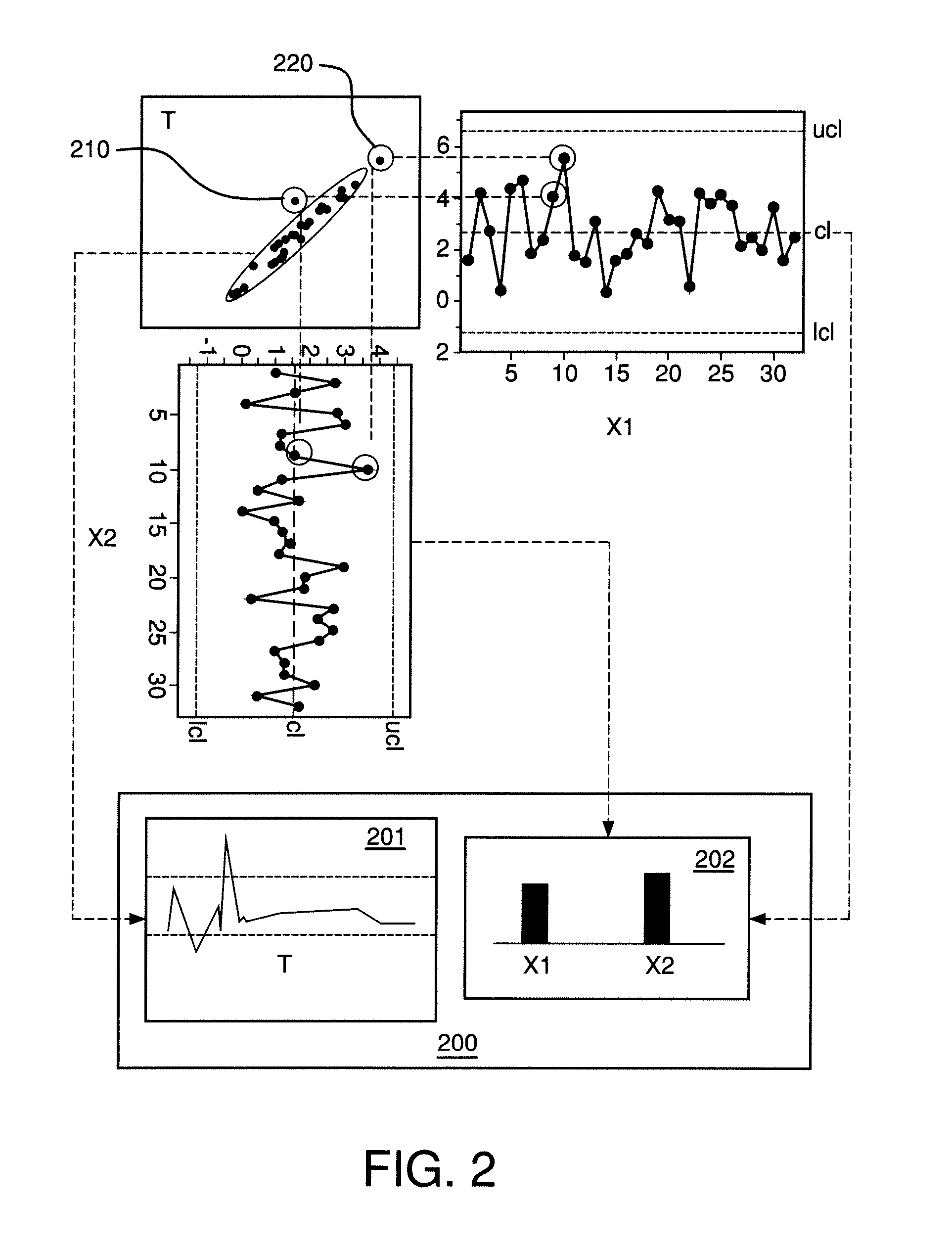
[0016]Systems and methods are provided to allow for remote monitoring and / or advisory control of a process plant using an interactive interface. A system according to the present invention may receive process monitoring data and construct a multivariate model of the process. Based on the multivariate model, a user interface may be presented to a user, who may be geographically remote from the process being monitored. The user interface may present various data, such as composite variables generated as part of the model, the contributions of various process variables to the model, time-based displays of the model and aspects of the model, and other data. Process monitoring data may be received in real time, and the user interface may be updated in real time.

[0017]FIG. 1 shows a schematic representation of an exemplary process plant, computer system, and user interface according to the invention. A process plant 100 may include multiple entities 110, 120, 130, 140 that may be monitore...


PUM


Abstract

Systems and methods are provided that allow a user to monitor, diagnose, and configure a process. A user interface may be presented that displays data received from process monitors, sensors, and multivariate models. The user interface may be interactive, allowing a user to select which composite and multivariate models are displayed. The user interface and multivariate model may be constructed and updated in real time. The user interface may present various data and interfaces, such as a representation of a composite variable in a multivariate model, a representation of the contribution of process variables to the composite variable, and a representation of a subset of the process variables. The user may select a point of the composite variable for analysis, and the interface may indicate the contribution and values of process variables at the selected point. The interface may be transmitted to a remote user.

Description

CROSS-REFERENCE TO RELATED APPLICATIONS[0001]This application claims the benefit of U.S. Provisional Application No. 60 / 856,757 filed Nov. 3, 2006, the disclosure of which is incorporated by reference in its entirety.BACKGROUND OF THE INVENTION[0002]Process control systems, such as those used in the chemical processing and supply fields, typically collect a wide variety of data within a process plant environment. This data is often stored and used to identify faults and potential upcoming faults in the system. For example, the data may be examined after a process failure to identify a problem that resulted in an unusable batch of material, or to identify a component that failed or is expected to fail within a specific time frame.[0003]Automated process control systems often are used to manage groups of sensors in a process plant. These process control systems typically monitor conditions in a process plant environment, and adjust process parameters based on conditions observed by th...

Claims


Application Information

Patent Timeline
Patent Type & Authority Patents(United States)
IPC IPC(8): G06F17/40G05B15/02G05B17/02G06F19/00
CPCG05B17/02G05B23/0254G05B2219/31478G05B2219/31457G05B2219/31477G05B2219/13G05B2223/06
Inventor ESMAILI, ALIMEHTA, SANJAYNEOGI, DEBASHISVALENZUELA, CARLOS A.
Owner AIR PROD & CHEM INC
Learn More