Near video-on-demand signal receiver

a video signal and receiver technology, applied in the field of video signal receivers, can solve the problems of distributors not being able to collect royalty payments for each reproduction of video programs, distributors lack effective control over the dissemination of video cassette tapes or discs to other consumers, and limited subscriber's viewing of video programs

Inactive Publication Date: 2009-10-20
SONY CORP
View PDF29 Cites 25 Cited by
  • Summary
  • Abstract
  • Description
  • Claims
  • Application Information

AI Technical Summary

Benefits of technology

[0012]Still another object of the present invention is to provide a near video-on-demand signal receiver capable of pausing the display of a video program transmitted by a broadcaster and resuming display of the program from that point without additional delay.

Problems solved by technology

However, a major disadvantage of this system is that the distributor lacks effective control over the dissemination of the video cassette tape or disc to other consumers by secondary sale of the cassette tape or disc or by copying of the video program to another cassette tape.
Consequently, the distributor is unable to collect a royalty payment for each reproduction of the video program.
Without the benefit of a recording device, the subscriber's viewing of the video program is limited to the specific interval during which the program is broadcast.
All too often, the broadcast schedule for the particular program is incompatible with the subscriber's own personal schedule.
However, the near video-on-demand system still suffers the drawback of not providing a “pause” function which allows the viewer to interrupt display of the video program for a period of time.
Clearly, such a solution is less than optimal.
Another deficiency of the near video-on-demand system is the variable delay between a subscriber's ordering of a program and the availability of that program for viewing.
Certainly, the inherent delay makes such a system less convenient than a video-on-demand system which displays the desired video programming immediately.

Method used


Image

  • Near video-on-demand signal receiver
  • Near video-on-demand signal receiver
  • Near video-on-demand signal receiver

Examples


Embodiment Construction

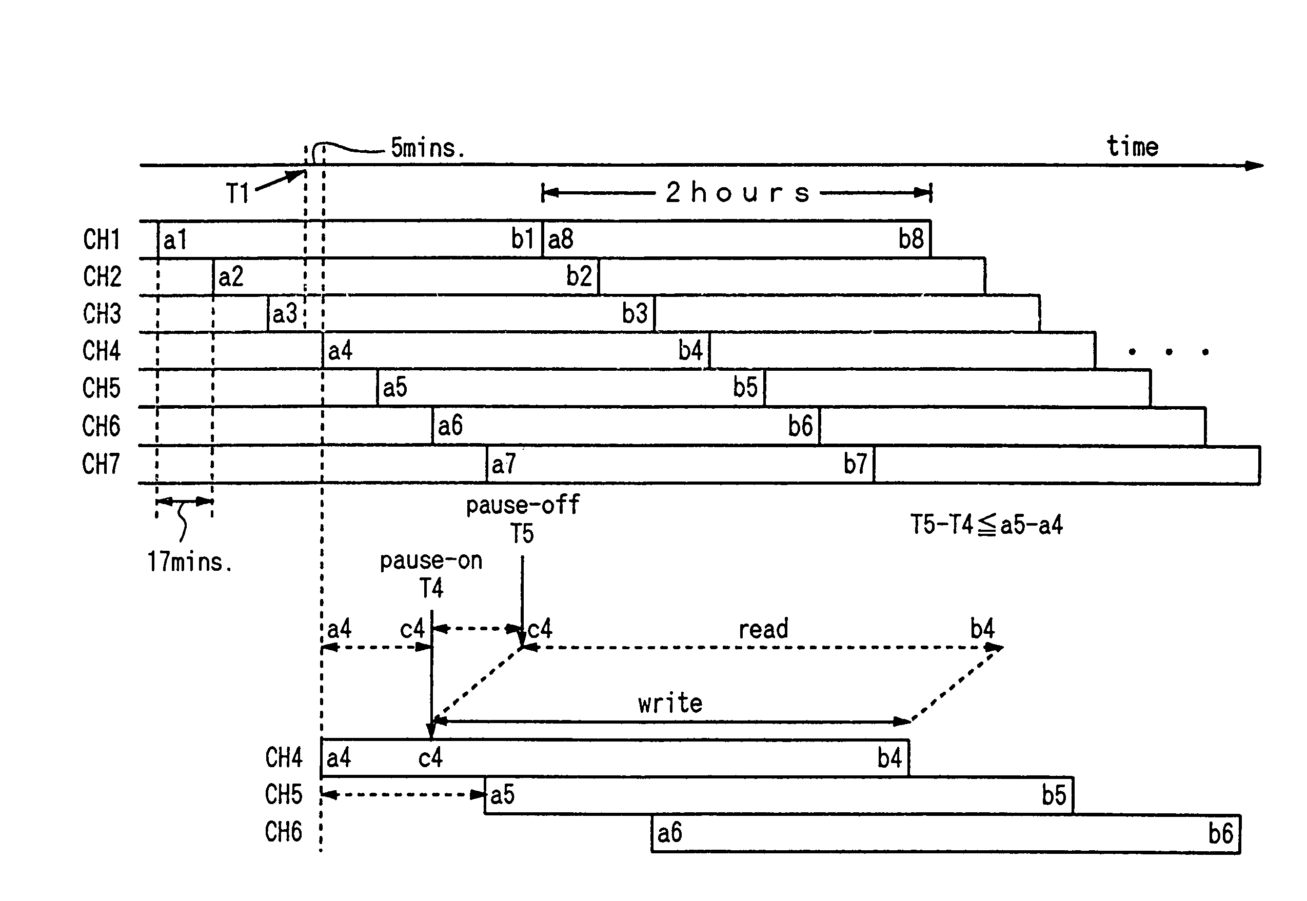
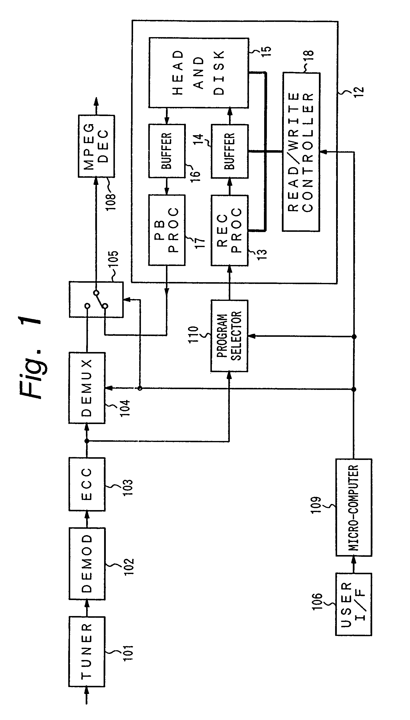
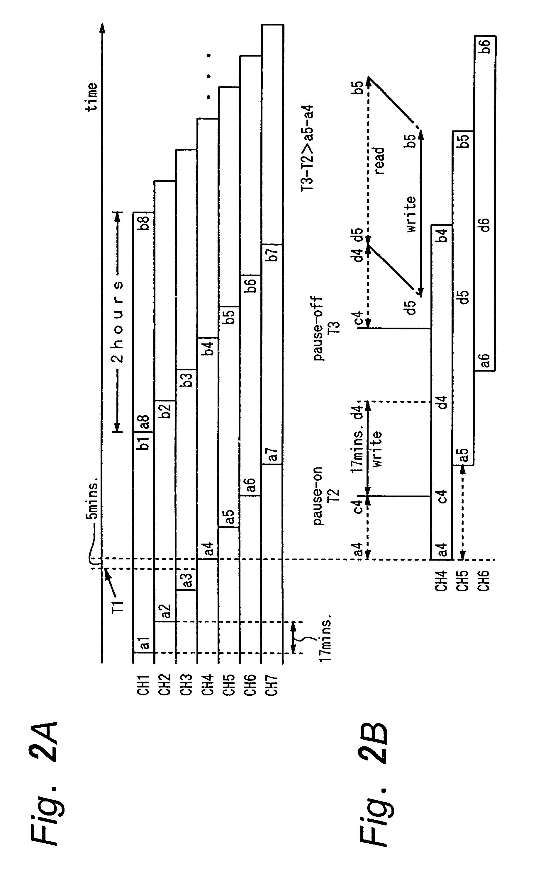
[0023]In FIG. 1, a near video-on-demand signal receiver according to the present invention is illustrated. The video signal receiver comprises a tuner 101, a demodulator 102, an error correction circuit 103, a demultiplexer 104, a switch 105, a decoder 108, a user interface 106, a microcomputer 109, a program selector 110, and a buffer memory apparatus 12. The receiver receives, decodes, and selectively displays video signals supplied by a broadcaster, utilizing buffer memory apparatus 12 to store certain portions of one or more video programs. By storing a portion of a selected video program, the receiver can display the stored portion of the program while awaiting or receiving transmission from the broadcaster of a subsequent portion of the program.

[0024]Tuner 101 receives input digital video signals, selects particular video signals, and supplies the selected signals to demodulator 102. Preferably, input digital video signals are satellite broadcast digital video signals acquired...


PUM


Abstract

A video signal receiver receives a plurality of video channels simultaneously carrying, offset by a transmission interval, a single video program, selects one channel from which to obtain the program for display to a user, and achieves a pause function in the display of the transmitted video program by temporarily storing a segment of the video program equal to the length of the transmission interval and obtaining the remainder of the program at a later time from the same or another channel.

Description

[0001]This is a continuation of application Ser. No. 08 / 840,199, filed Apr. 11, 1997, now U.S. Pat. No. 5,990,881, which is a division of application Ser. No. 08 / 520,564 filed on Aug. 28, 1995, now U.S. Pat. No. 5,729,280.BACKGROUND OF THE INVENTION[0002]This invention relates to a video signal receiver for a near video-on-demand broadcast system.[0003]Commonly, video programming has been provided to consumers through fundamentally different distribution systems. In one, video programs are recorded on individual video cassette tapes (or video discs) which are sold or rented to consumers. Conveniently, the consumer may view the recorded video program at the time of his choosing and may pause (or temporarily halt) reproduction of the video program at any time for an arbitrary length of time. However, a major disadvantage of this system is that the distributor lacks effective control over the dissemination of the video cassette tape or disc to other consumers by secondary sale of the c...

Claims


Application Information

Patent Timeline
Patent Type & Authority Patents(United States)
IPC IPC(8): H04N7/173H04N5/91H04N5/93H04N5/76H04N5/765H04N5/907H04N5/937H04N7/14
CPCH04N5/44H04N7/17309H04N7/16H04N5/4448H04N5/4401H04N21/26275H04N21/4333H04N21/47208H04N21/47211H04N21/426H04N21/433
Inventor INOUE, HAJIMEKUBOTA, YUKIONAGASHIMA, TOSHIMICHISHIMAZU, AKIRAKANOTA, KEIJI
Owner SONY CORP
Why Eureka
Try Eureka