

Mixer tap
a technology of mixer taps and mixers, applied in the direction of multiple way valves, valve details, domestic plumbing, etc., can solve the problems of large tap assembly footprint on the work surface, large housings, and aesthetically pleasing, and achieve the effect of avoiding excessive bending
Inactive Publication Date: 2009-10-27
HORNBEAM IVY
View PDF17 Cites 15 Cited by
- Summary
- Abstract
- Description
- Claims
- Application Information
AI Technical Summary
Benefits of technology
"The present invention provides a mixer tap assembly with a control mechanism for controlling input and output from a mixing chamber. The assembly includes a mixing chamber, fluid outlet, output conduit, and a mix controller and mix actuator for controlling fluid input and output. The components of the assembly are positioned relative to the work surface and can be mounted on or above the surface. The assembly can be mounted in a sink unit or on a separate control panel. The technical effects of the invention include a smaller size and more aesthetically pleasing appearance of the assembly components, as well as improved control over fluid flow and more efficient use of space on the work surface."
Problems solved by technology
Method used
View moreImage
Smart ImageViewing Examples

Examples
third embodiment
[0082]In the tap assembly 100 of the third embodiment, the housing 26 includes a flat base plate 106 which can be mounted on the wall 102 using screws 108. The output conduit 18 enters the cut out 25 in the tube 24 behind the wall 102 and is therefore guided horizontally through the wall into a conventional spout 104 to terminate at spray head 34.
[0083]Similar to the second embodiment, the third embodiment uses the single lever mixer valve 74, but in this case, the valve 74 is held in a horizontal configuration, with the lever 76 extending substantially horizontally.
second embodiment
[0084]The inner control sleeve 72 is movable axially (horizontally) and rotatably by the control lever 30 on the housing 26 using the same mechanism as the
Login to View More PUM
 Abstract
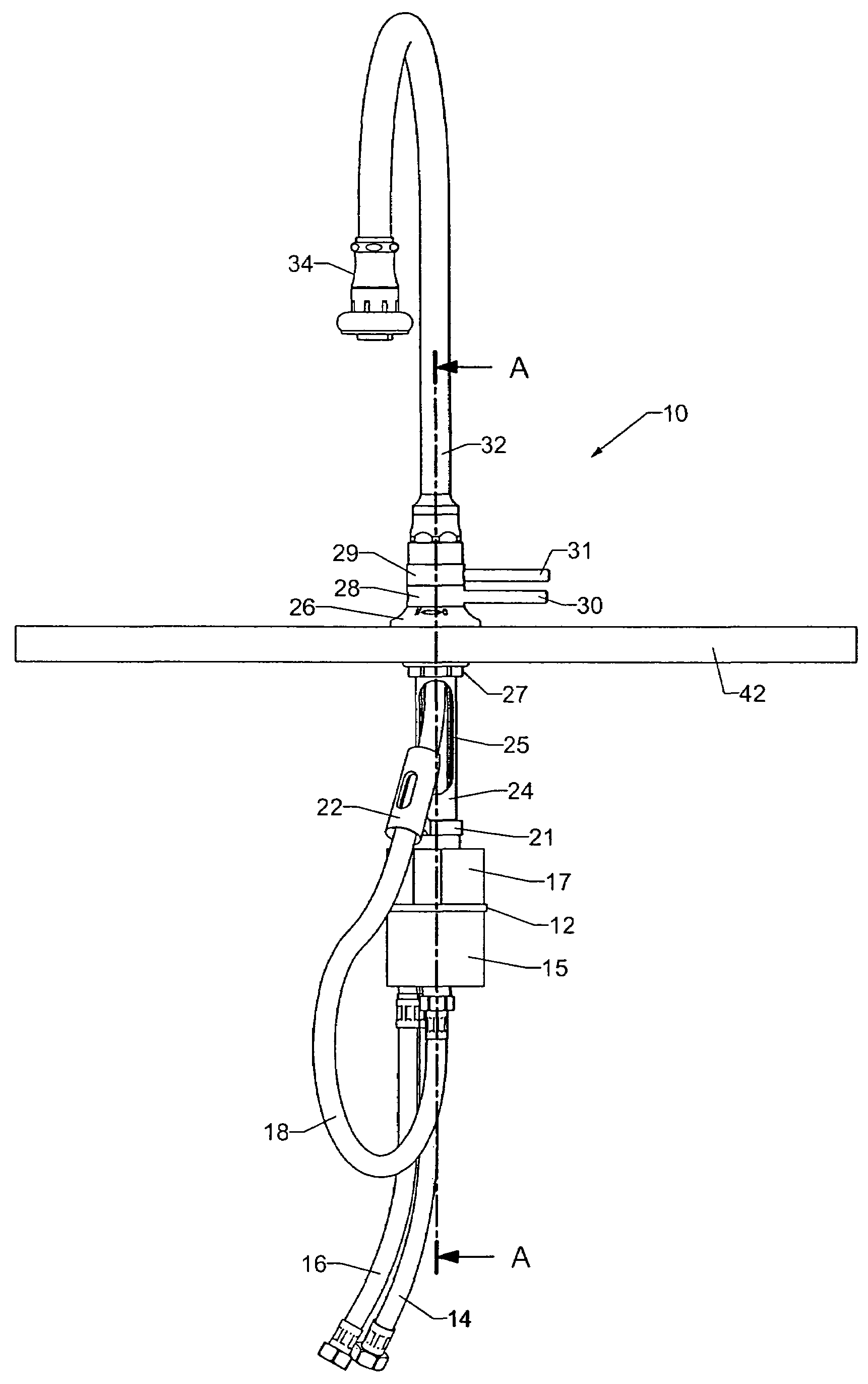
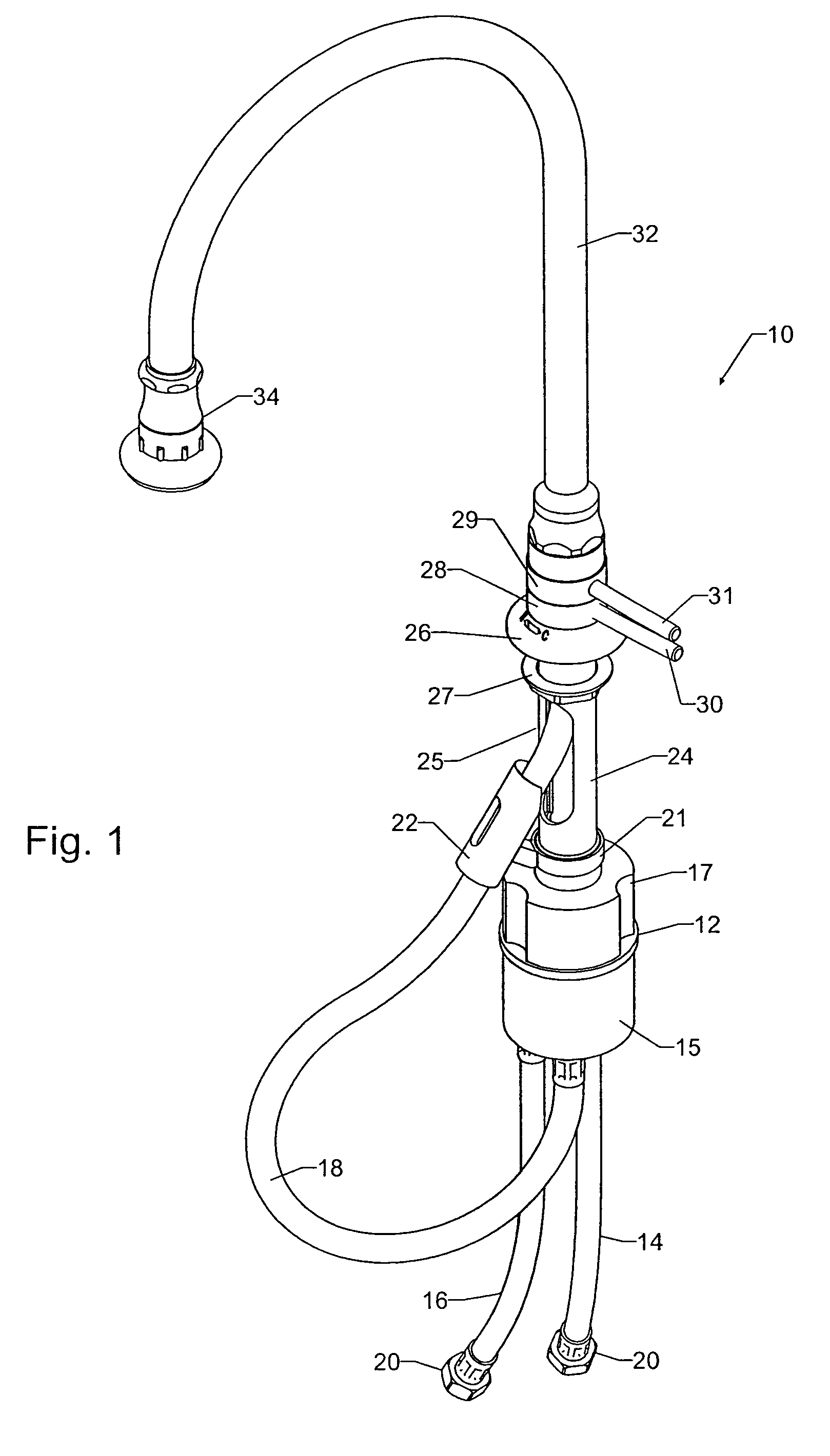
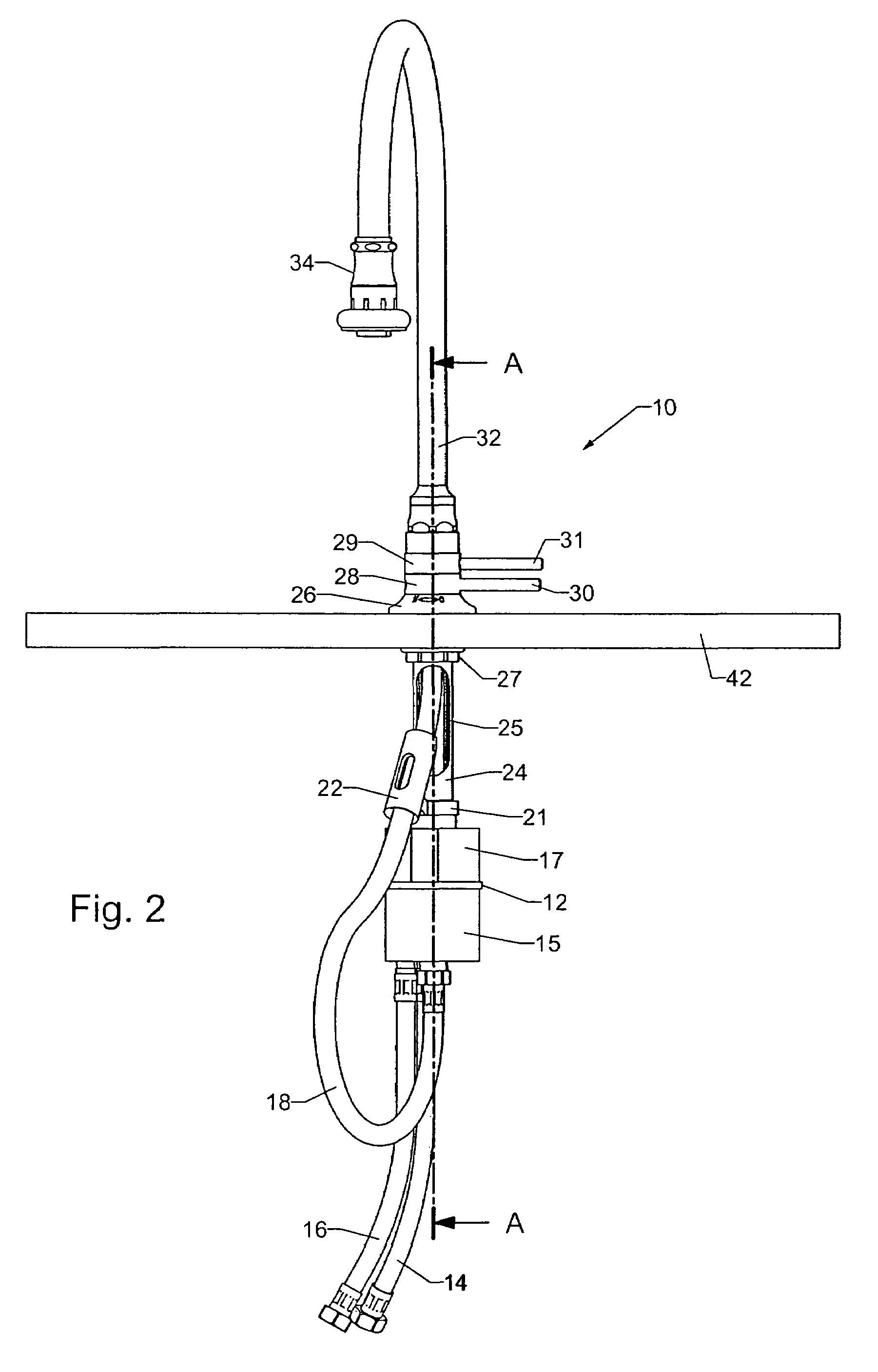
A mixer tap assembly is shown which has a mixing chamber for mixing fluids from two inputs, and a mix controller to control the ratio of fluid flow into the mixing chamber from the inputs. The mix controller includes a mix actuator which operates a mix control apparatus, such as a rotatable sleeve, which is connected to a mix valve apparatus associated with the mixing chamber. The mix actuator and a fluid outlet are mountable on or above a work surface via a mounting apparatus, while the mixing chamber is mountable below the work surface. Furthermore, the mix control apparatus and an output conduit, between the fluid outlet and the mixing chamber, pass through a bore in the mounting means, so minimizing the footprint of the mixer tap assembly on the work surface.
Description
BACKGROUND OF THE INVENTION[0001]1. Field of the Invention[0002]The present invention relates to mixer taps, i.e. taps with a plurality of fluid inputs which are mixable to be ejected from one or more common outputs. For example, mixer taps are used on kitchen sinks to provide a single water supply with controllable temperature. The present invention is applicable to mixer taps having a pull-out or pull-down spray facility, i.e. where the or an additional fluid outlet is detachable from the main unit to give flexible user-directable flow.[0003]2. Summary of the Prior Art[0004]Mixer taps are well known. Typically, fluid input from a plurality of sources (usually hot and cold water supplies) is controllably conveyed to a mixing chamber, where the fluid is mixed and ejected through an output spout. Such mixer taps commonly use a single lever mixing valve to control the flow rate and temperature of the ejected water. Temperature is controlled by adjusting the ratio of hot to cold inputs...
Claims
Login to View More Application Information
Patent Timeline
 Patent Type & AuthorityPatents(United States)
IPC IPC(8): F16K11/18E03C1/04F16K31/53
CPCE03C1/04F16K31/53F16K19/006F16K11/18E03C2001/0415Y10T137/86815Y10T137/87056Y10T137/0491Y10T137/86549Y10T137/87088
InventorHERRING, WILLIAM PETERMOORE, JAMES
OwnerHORNBEAM IVY