
Demagnetizing Method

Active Publication Date: 2008-08-21
MAURER ALBERT
View PDF4 Cites 3 Cited by
  • Summary
  • Abstract
  • Description
  • Claims
  • Application Information

AI Technical Summary

Benefits of technology

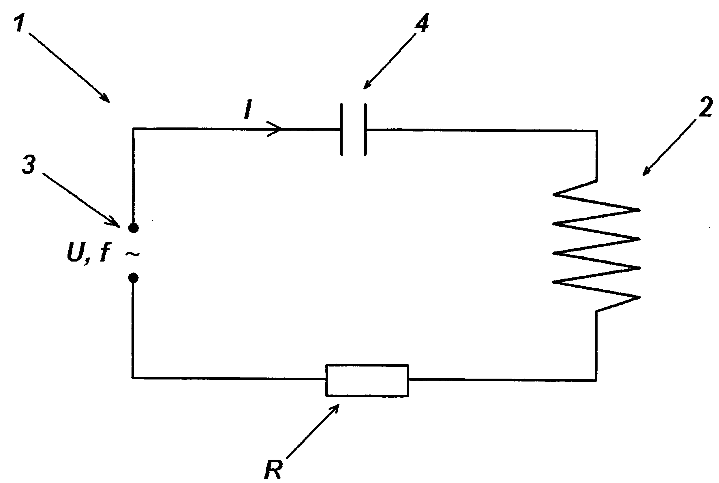
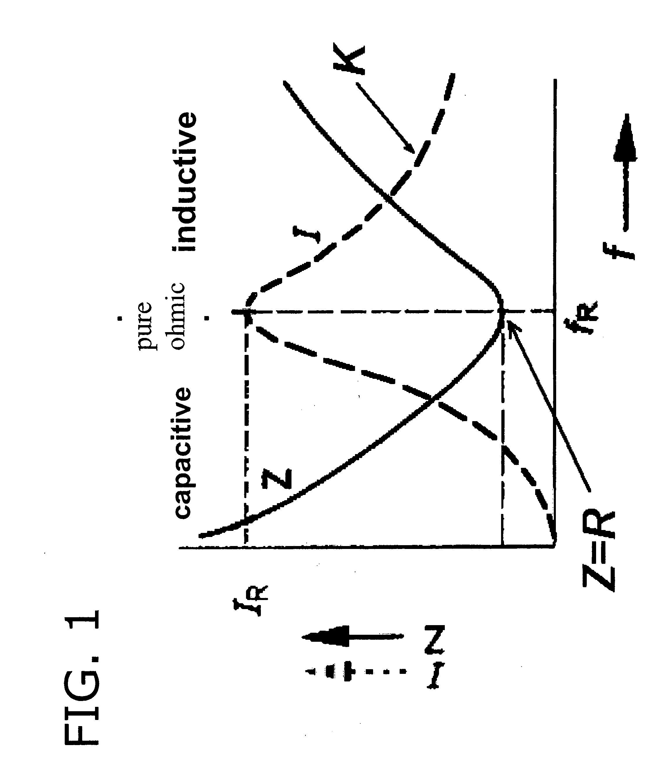
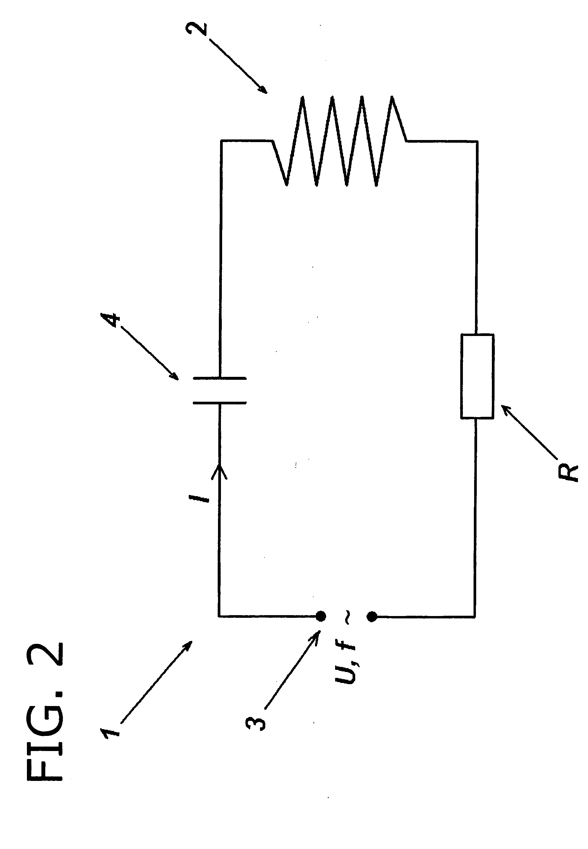
[0011]Through this method, without additional technical outlay in the form of control / regulating circuits or on / off sequences for filled / empty coils, a demagnetization coil may be operated at a fill level from 0 to nearly 100% under largely constant processing conditions. The magnetic flux of the demagnetization coil is thus exploited in the best possible way. The demagnetization coil may tightly enclose the material and may be kept relatively small in its dimensions. Optimal demagnetization in regard to energy efficiency thus results.

Problems solved by technology

The first problem arises due to the inductance, which has a direct relationship to the function of the coil.
The reduction of the frequency as a measure for reducing the required apparent power thus also results in a correspondingly reduced throughput.
This solution may only be implemented at fixed frequency, however, if the inductance of the coil remains constant, which is not ensured upon charging with material.
The inductance of the coil, which is a function of the charging and the material to be demagnetized, represents the second problem.
Upon supply with constant voltage and frequency, the absorbed current of the coil decreases as a function of its charging, which results in altered conditions of the demagnetization process.
The differing inductance of the demagnetization coil is thus taken into consideration by automatic tracking of the frequency and both problems are solved, but at the cost of a significant outlay for the circuit.

Method used


Image

  • Demagnetizing Method
  • Demagnetizing Method
  • Demagnetizing Method

Examples


Embodiment Construction

[0010]The present invention relates to a significantly simpler circuit in relation thereto, which on one hand covers the large demand for apparent power of the demagnetization coil and on the other hand takes its variable inductance into consideration in such a way that the reproducible conditions are provided for the demagnetization procedure, independently of the charging.

[0011]Through this method, without additional technical outlay in the form of control / regulating circuits or on / off sequences for filled / empty coils, a demagnetization coil may be operated at a fill level from 0 to nearly 100% under largely constant processing conditions. The magnetic flux of the demagnetization coil is thus exploited in the best possible way. The demagnetization coil may tightly enclose the material and may be kept relatively small in its dimensions. Optimal demagnetization in regard to energy efficiency thus results.

[0012]A further object of the present invention is to provide a failsafe and ne...


PUM


Abstract

A method is presented for demagnetizing ferromagnetic components in an alternating field of an externally excited electrical series resonant circuit. A supply voltage having an excitation frequency (f) is applied in parallel to a demagnetization coil having a no-load inductance of the series resonant circuit, because of which an alternating current (I) flows through the series resonant circuit (1), which generates a magnetic alternating field. In the event of suitable selection of the excitation frequency (f) in such a way that the product of the excitation frequency (f) in Hz multiplied by the no-load inductance (L0) in Henry is f*L0≧0.22 Hz*H, the excitation frequency is in an operating range (5) and the series resonant circuit (1) may be used without further regulation technology to demagnetize components which are led through the inner chamber of the demagnetization coil (2) and form a fill level. If the excitation frequency (f) is selected accordingly, continuous operation is possible, in which the resonant frequency (fR) of the series resonant circuit (2) is not reached even at a high fill level.

Description

TECHNICAL AREA[0001]The present invention describes a method for demagnetizing ferromagnetic components in a magnetic alternating field of an externally excited series resonant circuit having an associated resonant frequency, comprising at least one demagnetization coil having a no-load inductance, which is connected in series to at least one first capacitor having an associated capacitance and in parallel to a voltage source, a supply voltage having an adjustable excitation frequency and fixed voltage amplitude being able to be applied.PRIOR ART[0002]Elongate coils, through which the material to be demagnetized is continuously conveyed, are used for demagnetizing ferromagnetic parts. The coil is connected to an AC voltage of constant frequency and amplitude, which is typically drawn directly from the mains. The material to be demagnetized is subjected to an increasing magnetic flux of alternating direction upon entry into the coil, until a maximum of the field is reached in the coi...

Claims


Application Information

Patent Timeline
IPC IPC(8): H01F13/00
CPCH01F13/006
Inventor MAURER, ALBERTROHNER, MAREK
Owner MAURER ALBERT
Learn More