Sounding tool for cheering

Inactive Publication Date: 2009-10-27
SHARP SANGYO
View PDF29 Cites 3 Cited by
  • Summary
  • Abstract
  • Description
  • Claims
  • Application Information

AI Technical Summary

Benefits of technology

[0048]The present invention has the following effects.
[0049]According to the invention as recited in the aforementioned Item [1], the sounding tool has a hollow cover body having a shape imitating an object or a character for enhancing interest, and clapping bars are disposed between the front and rear wall portions of the cover body so that the clapping bars vertically penetrate the cover body with the cover body positioned at longitudinal intermediate portions of the clapping bars. Accordingly, the size of the cover body can be set corresponding not to one of the clapping bars but to both the clapping bars. Therefore, the freedom of design of the cover body can be increased, resulting in enhanced interesting nature. Furthermore, since a bigger cover body can be designed, the cover body can be emphasized.
[0050]Furthermore, since both the clapping bars vertically penetrate the cover body between the front and rear wall portion of the cover body, the center of gravity of the cover body can be positioned on the central axis extending along the up-and-down direction of the clapping bars or at a portion vicinity thereof. As a result, there is an advantage that the sounding tool can be stably disposed on a table or desk in a room for ornamental purposes.
[0051]Furthermore, right clapping bar guide groove portions and left clapping bar guide groove portions are provided, respectively, at a righ

Problems solved by technology

Therefore, it is required to set the size of the mascot doll in accordance with the size of one of the clapping bars, which limits the degree of design freedom of the

Method used


Image

  • Sounding tool for cheering
  • Sounding tool for cheering
  • Sounding tool for cheering

Examples


Embodiment Construction

[0082]Next, some embodiments of the present invention will be explained with reference to the attached drawings.

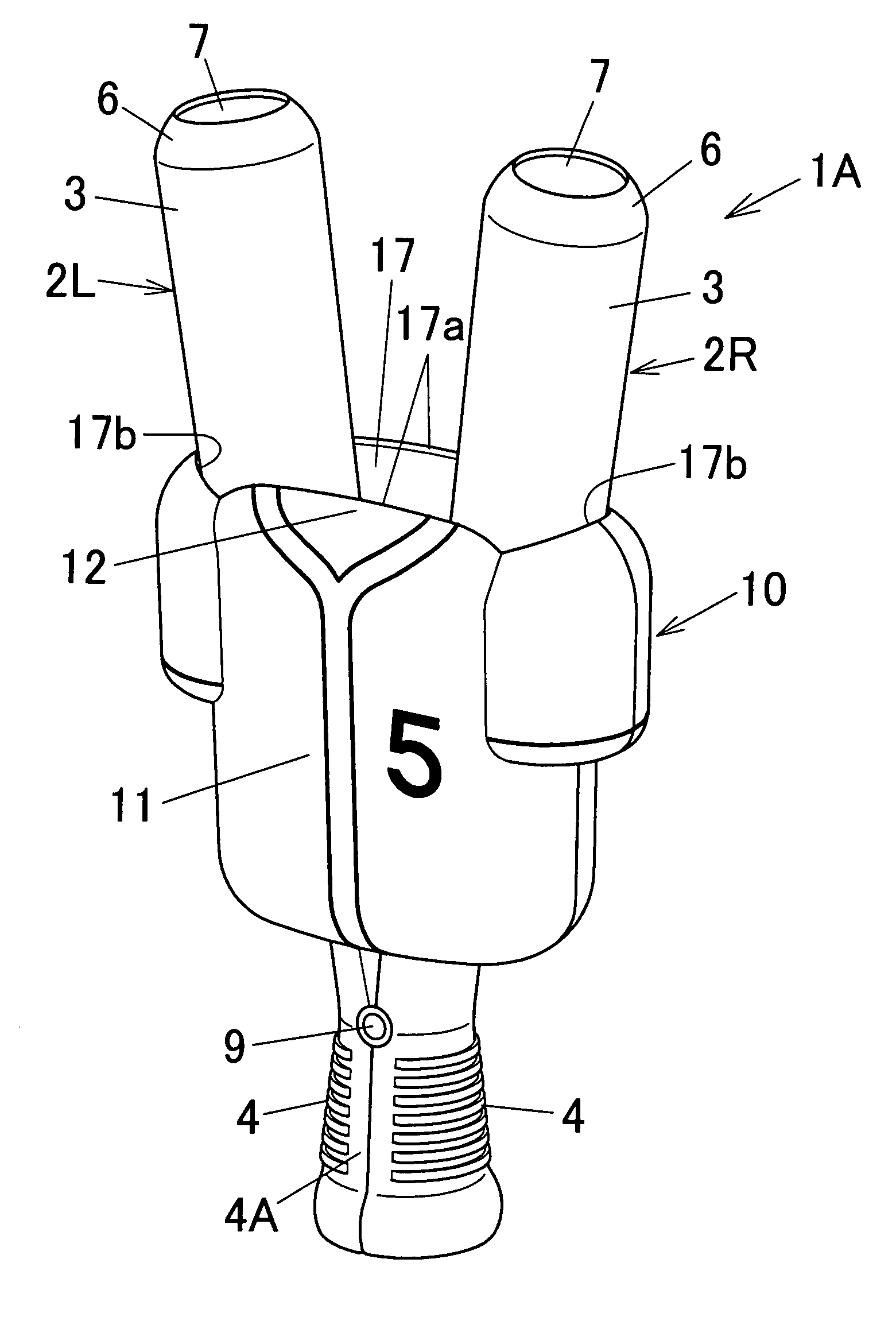
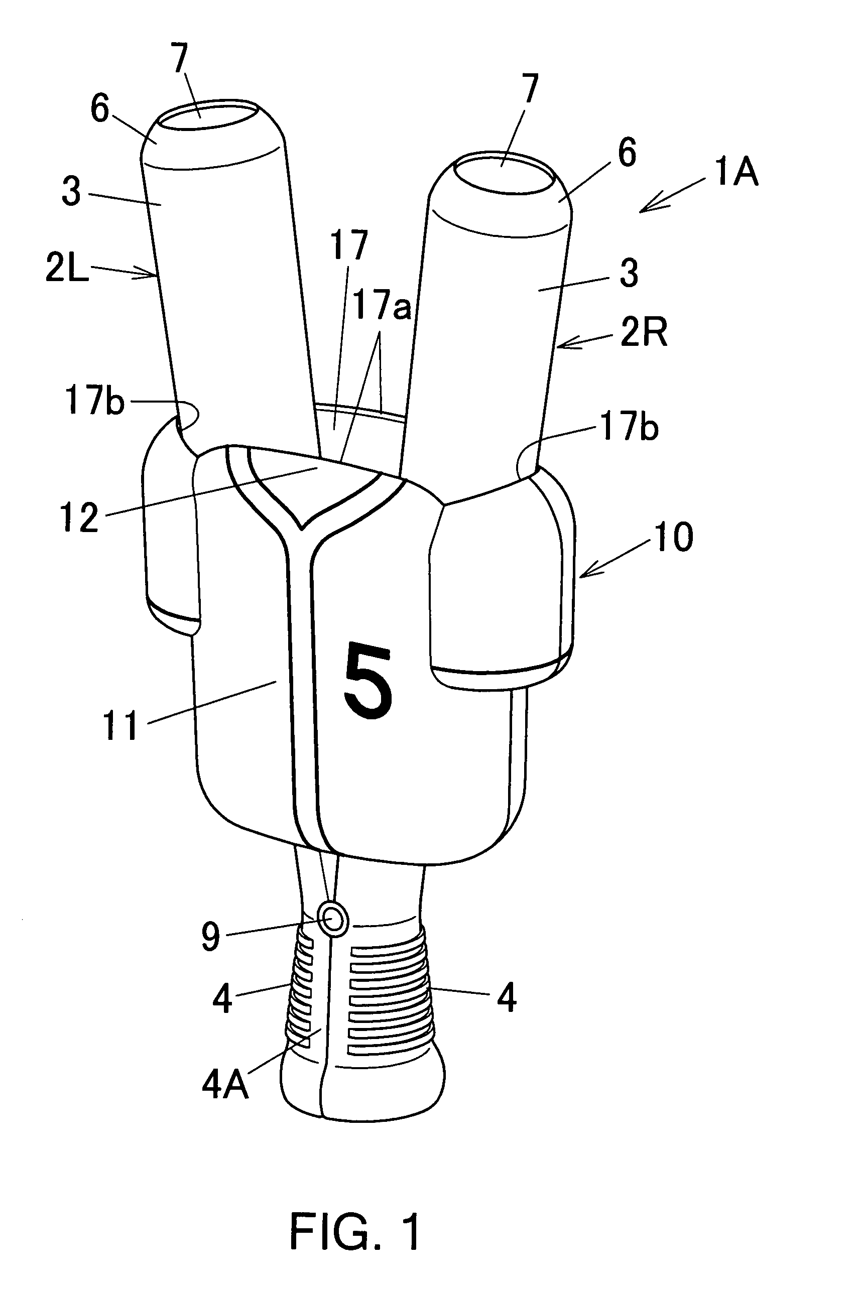
[0083]FIGS. 1 to 6 are explanatory views showing a sounding tool for cheering according to a first embodiment of the present invention. In FIG. 1, “1A” denotes a sounding tool for cheering according to the first embodiment. This sounding tool 1A is used to cheer for a baseball team at the time of watching baseball as sports.

[0084]This sounding tool 1A is equipped with a pair of right and left clapping bars 2R and 2L and a hollow cover body 10.

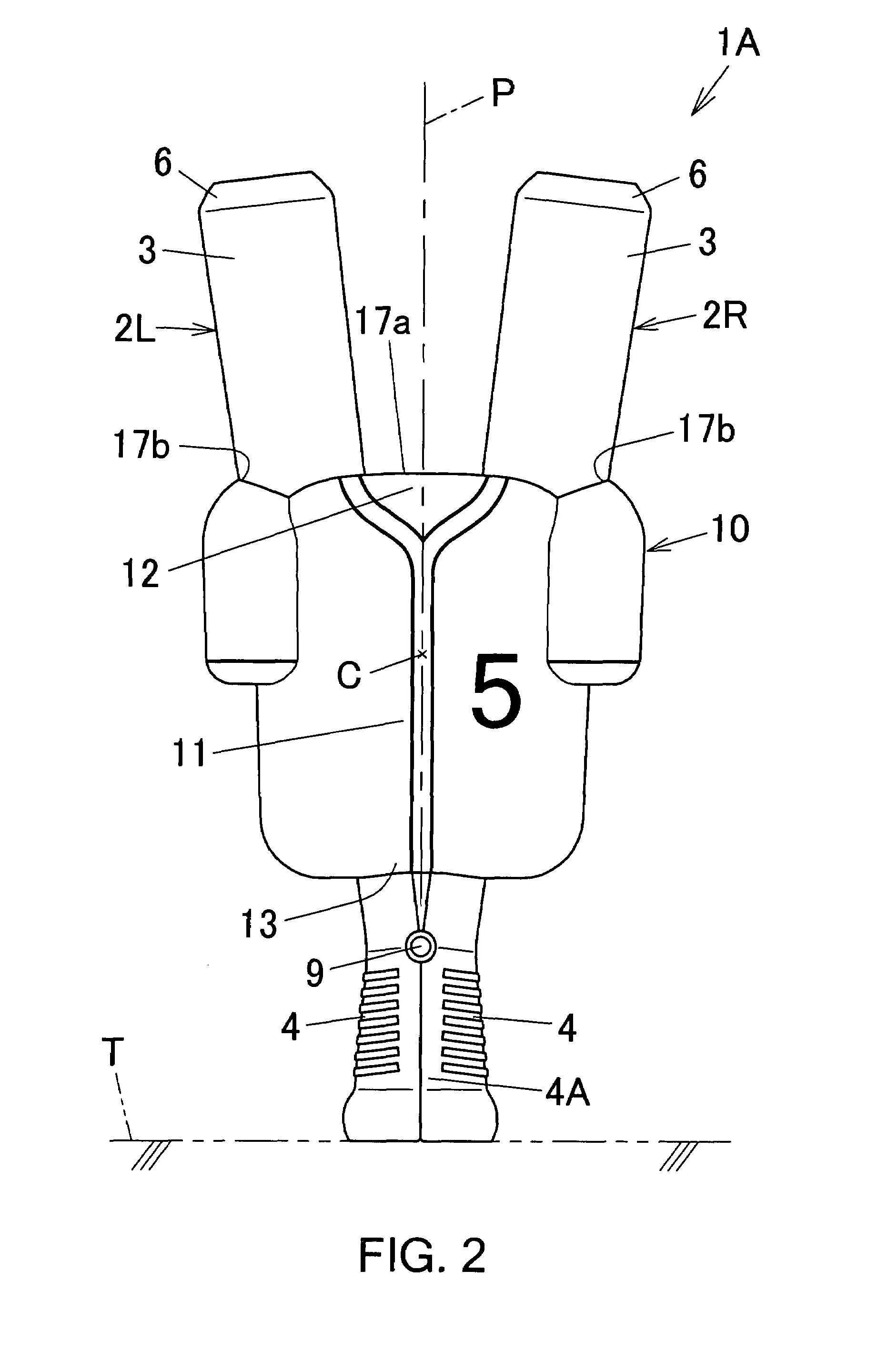
[0085]The cover body 10 is aplastic hollow molded article having a shape imitating a uniform of a favorite baseball team as an object for enhancing interest as shown in FIGS. 1 to 3.

[0086]This cover body 10 is divided into two halves, or a front half and a rear half, as shown in FIG. 4. The front wall portion 11 and the rear wall portion 11 of the cover body 10 are mutually connected with a plurality of screws 20 (four pieces of screw...


PUM


Abstract

A highly interesting sounding tool for cheering is provided. The sounding tool 1A comprises a pair of right and left clapping bars 2R and 2L, and a hollow cover body 10 having a shape imitating an object for enhancing interest. Both clapping bars 2R and 2L are pivotally joined at a position between the beating portion 3 and the gripping portion 4 such that the beating portions 3 and gripping portion 4 can be opened/closed. Both clapping bars 2R and 2L vertically penetrate the cover body 10 between the front and rear wall portions 11 and 11. Guide groove portions 15R and 15L are provided, respectively, on the inner right and left side surfaces of the front and rear wall portions 11 and 11 of the cover body 10 so as to be vertically apart from each other. Guide protruded portions 5R and 5L are provided, respectively, on the front and rear surfaces of the right and left clapping bars 2R and 2L so as to be vertically apart from each other. The guide protruded portions 5R and 5L are fitted in the guide groove portions 15R and 15L. When the guide protruded portions 5R and 5L move along the guide groove portions 15R and 15L, the beating portions 3 and 3 of the right and left clapping bars are guided in the opening and closing directions.

Description

TECHNICAL FIELD[0001]The present invention relates to a sounding tool for cheering typically used at the time of watching sport.BACKGROUND ART[0002]As a sounding tool for cheering used for cheering various sports, such as, e.g., baseball, volleyball, soccer, or basketball, a sounding tool having a pair of right and left clapping bars (the so-called clappers) pivotally connected with each other in an openable / closable manner is known. This sounding tool is configured to make a sound by repeatedly opening / closing the beating portions of the clapping bars to hit with each other at the time of cheering.[0003]The clapping bars of this kind of sounding tool are generally constituted by two megaphone halves. At the time of cheering with voice, this sounding tool is used as a megaphone in a state in which both the megaphone halves are opened in a V-shape (see, e.g., Patent Documents 1-6).[0004]Furthermore, in this kind of sounding tool, for the purpose of enhancing the interesting nature, i...

Claims


Application Information

Patent Timeline
IPC IPC(8): A63H5/00
CPCG10K3/00G10D13/06G10K11/08
Inventor KOBAYASHI, YUU
Owner SHARP SANGYO
Why Eureka
Try Eureka