Osteoarthritis knee orthosis

a knee joint and orthosis technology, applied in the field of knee braces, can solve the problems of joint pain and swelling, limitation of joint mobility, diminished joint space, etc., and achieve the effects of balancing joint space, improving knee joint alignment, and easy management of controls

Active Publication Date: 2009-10-27
NACE RICHARD NACE
View PDF11 Cites 34 Cited by
  • Summary
  • Abstract
  • Description
  • Claims
  • Application Information

AI Technical Summary

Benefits of technology

[0015]The present invention provides an osteoarthritis knee orthosis easily fabricated in a wide range of sizes for either knee (left or right) to treat either medial or lateral (varus or valgus) unicompartmental degeneration of the knee joint caused by osteoarthritis or osteoarthrosis with easily managed controls for setting the desired degree of flexion and extension. The knee orthosis of this invention will unload the pressure on the affected side of the knee joint, provide balanced joint space on both sides of the knee during ambulation, improve knee joint alignment, and can be adjusted as the condition of the knee improves or deteriorates to maintain joint space balance, an unloading effect on the affected side of the knee joint, and improved knee joint alignment during gait.
[0016]As alignment of the knee changes (joint space balance), the mechanism of the knee brace is adjusted by this invention so that joint space balance is continually maintained with joint rehabilitation. The current invention achieves this significant improvement with an adjustable dynamic fulcrum to allow the clinician to quickly and easily adjust the brace to maintain joint space balance as needed during the knee rehabilitation process.

Problems solved by technology

Repetitive use of the joints over the years can irritate and inflame the cartilage, causing joint pain and swelling.
In advanced cases, there is a total loss of cartilage cushion between the femur and tibia bones at the knee joint, leading to diminished joint space on the affected side of the knee resulting in pain and limitation of joint mobility.
Inflammation of the cartilage also can stimulate new bone outgrowths (spurs) to form around the joints causing increased pain and joint inflammation.
With irritation of the joint, bone spurs can form causing bits of bone and cartilage to break off which float inside the joint space further irritating the knee.
The knee then becomes imbalanced, with the knee bowing outwards.
Secondly, many osteoarthritis knee orthotics or braces are designed to prevent the “bone on bone” contact of the femur and tibia bones in the medial or lateral compartment of the knee joint as the patient bears weight during ambulation.
However, it is difficult to set the desired degrees of flexion and extension.
Although many of the existing knee braces containing locking hinge assemblies serve their intended purpose, difficulty in ease of setting the desired degrees of flexion and extension continues to be a problem.

Method used


Image

  • Osteoarthritis knee orthosis
  • Osteoarthritis knee orthosis
  • Osteoarthritis knee orthosis

Examples


Embodiment Construction

[0031]Throughout the following detailed description the same reference numerals refer to the same elements in all figures.

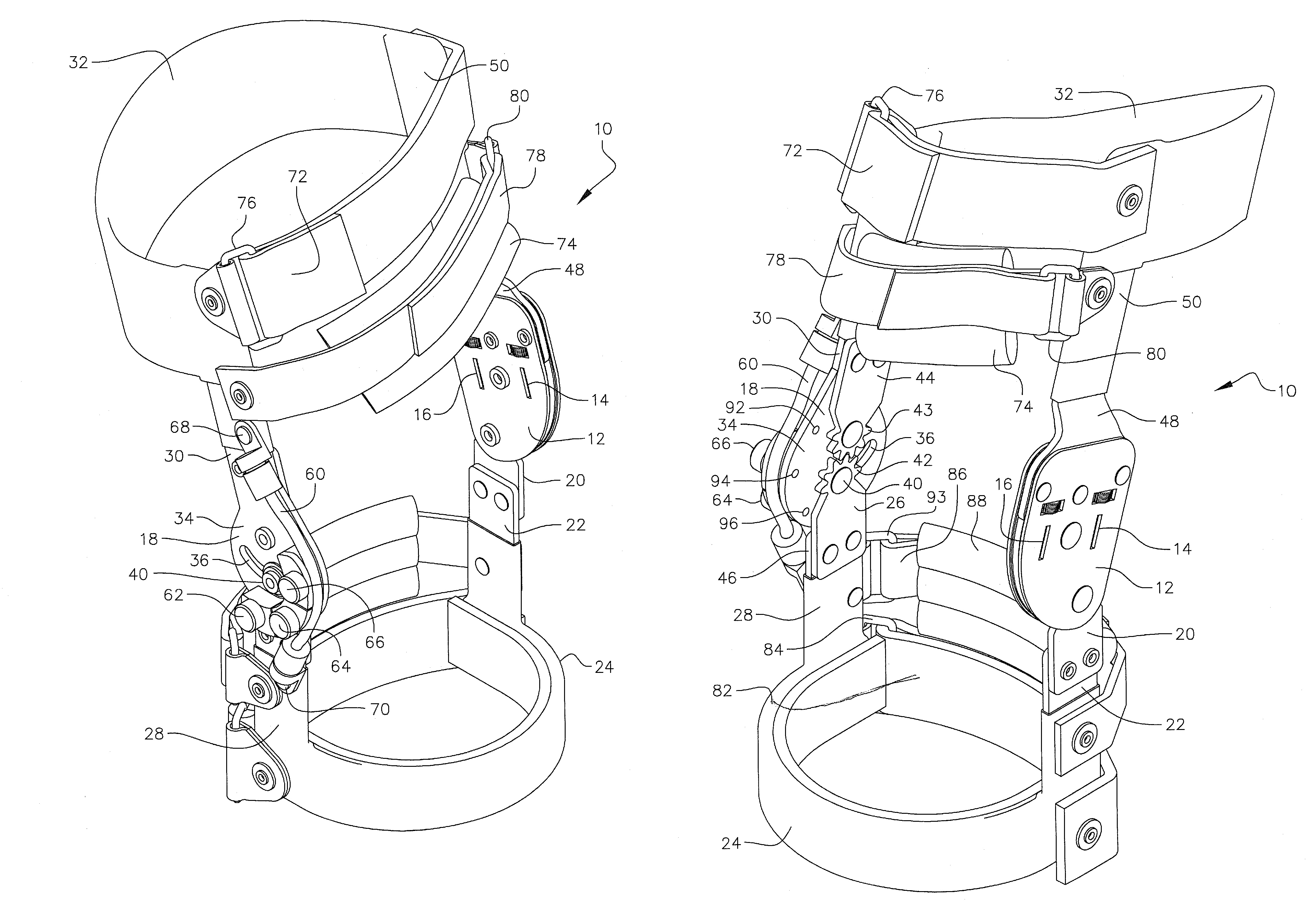
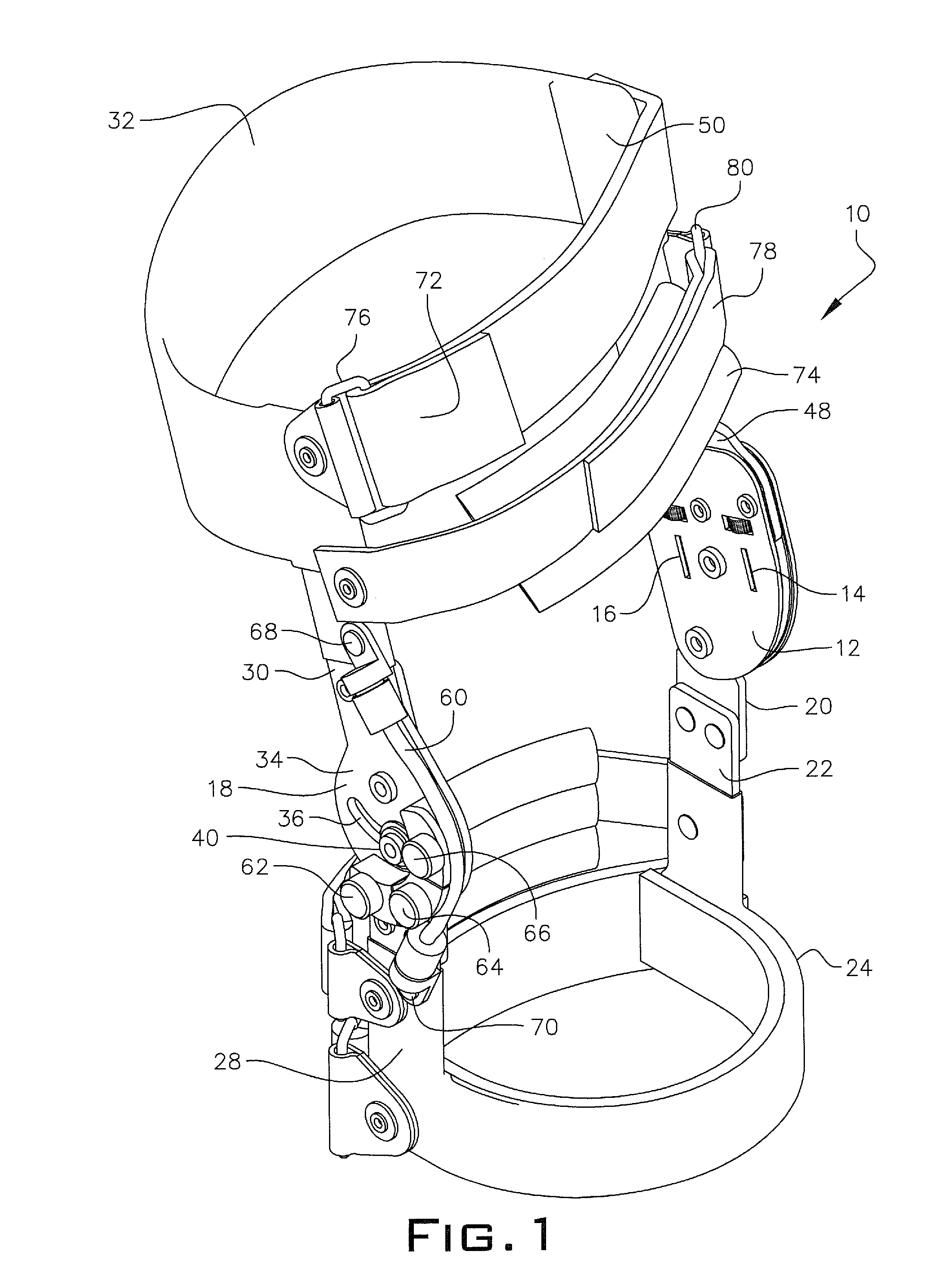
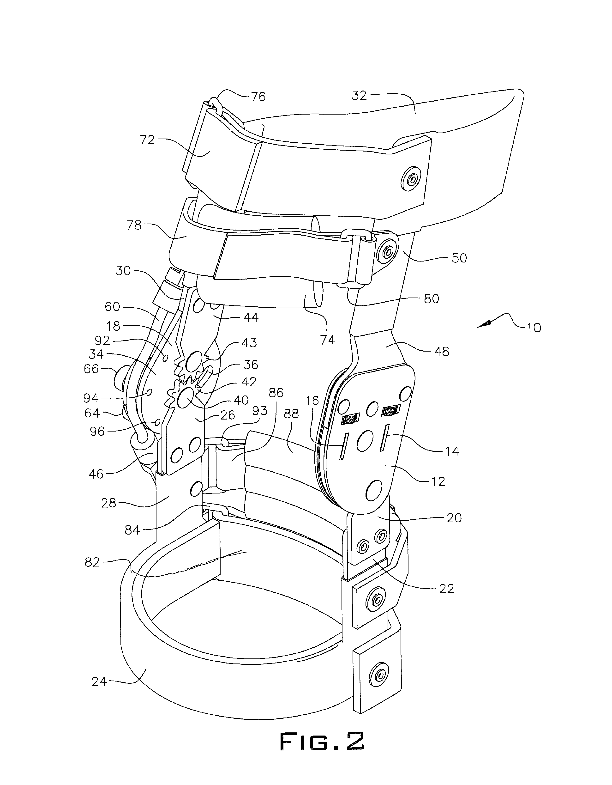
[0032]Referring to FIGS. 1 and 2, the osteoarthritis knee orthosis 10 (hereafter identified as OA), has a medial unicentric hinge 12 with flexion stop 14 and extension stop 16 at any setting. The medial unicentric hinge 12 is substantially parallel to a lateral polycentric adjustable tension offloading hinge 18. The bottom end 20 of medial hinge 12 is attached to a first upright member 22 integral with a rigid knee ring 24. A lower gear plate 26 of lateral hinge 18 is attached to a second upright member 28 integral with knee ring 24.

[0033]An upper arm 30 of the lateral hinge 18 connects at an upper end to a semi-rigid upper thigh cuff 32. A lower portion of the lateral hinge broadens out to a slotted hinge connector plate 34. A slot 36, in connector plate 34 contains a transverse shaft on rivet 40. The rivet 40 attaches a first star gear 42 to an inside surface o...


PUM


Abstract

A polycentric hinge is positioned on one side of the patient's knee and a unicentric hinge is positioned on a second side of the knee. A lower portion of the polycentric and unicentric hinge is attached to a knee cuff about a lower leg of the patient. An upper arm of the polycentric and unicentric hinge is attached to a thigh cuff, the upper arm of the unicentric hinge being longer than the upper arm of the polycentric hinge. The upper arm of the unicentric hinge has a 15° to 20° set back angle when the patient's leg is straight. The polycentric hinge has a slotted central plate with star gears engaging a back portion and multiple movable blocks mounted in screw holes on a front edge of the slotted plate supporting an elastic band having a fulcrum point on the polycentric hinge at a lower and upper end.

Description

FIELD OF THE INVENTION[0001]The invention relates to knee braces. More particularly, it refers to an offset double upright knee brace.BACKGROUND OF THE INVENTION[0002]Orthotic devices and appliances commonly referred to as “orthotics,” have been utilized for many years by orthotists, physical therapists, and occupational therapists to assist in the rehabilitation of patient's joints and associated limbs or adjacent skeletal parts of the patient's body.[0003]Webster's New College Dictionary defines “orthotics” as a branch of mechanical and medical science that deals with the support and bracing of weak or ineffective joints or muscles.[0004]Orthotics or limb braces have been designed to support and protect the joint, alleviate pain associated with joint movement, and to rehabilitate the joint over time with orthotic use.[0005]Primary osteoarthritis is usually related to aging. With aging, the water content of the cartilage increases and the protein makeup of the cartilage degenerates...

Claims


Application Information

Patent Timeline
Patent Type & Authority Patents(United States)
IPC IPC(8): A61F5/00
CPCA61F5/0123A61F2005/0179A61F2005/0139
Inventor NACE, RICHARD A.
Owner NACE RICHARD NACE
Why Eureka
Try Eureka