
Fastener module controlled by magnetic force

a technology of fastener module and magnetic force, which is applied in the direction of portable computer details, electric apparatus casings/cabinets/drawers, instruments, etc., can solve the problems of inconvenience in use, negative affect the whole appearance of the body, and easy damage, so as to facilitate the opening of foldable electronic devices

Inactive Publication Date: 2009-10-27
COMPAL ELECTRONICS INC
View PDF15 Cites 2 Cited by
  • Summary
  • Abstract
  • Description
  • Claims
  • Application Information

AI Technical Summary

Benefits of technology

The present invention provides a fastener module for a foldable electronic apparatus that allows the user to easily open the apparatus with minimal force. The module includes a first fastener with magnetic susceptibility, a second fastener, a control circuit, a sensor, and a magnetic element. The sensor triggers the control circuit when the apparatus is closed, and the magnetic element exerts a magnetic force on the first fastener to fasten it with the second fastener. After a predetermined time, the control circuit stops exerting the magnetic force on the first fastener. The control circuit controls the magnetic element to determine whether to exert the magnetic force on the first fastener. The fastener module also includes a release mechanism to release the fastening between the first and second fasteners. The magnetic element is an electromagnet that stops exerting the magnetic force when the apparatus is closed, making it easy to open with minimal force.

Problems solved by technology

However, since the hook protrudes from the surface of the body of the notebook computer, it negatively affects the whole appearance of the body and will be easily damaged.
However, the magnetic force provided by the permanent magnet is a continuous magnetic force, so that the user must exert a force larger than the magnetic force of the permanent magnet to open the notebook computer, thereby causing inconvenience in the usage.

Method used


Image

  • Fastener module controlled by magnetic force
  • Fastener module controlled by magnetic force
  • Fastener module controlled by magnetic force

Examples


Embodiment Construction

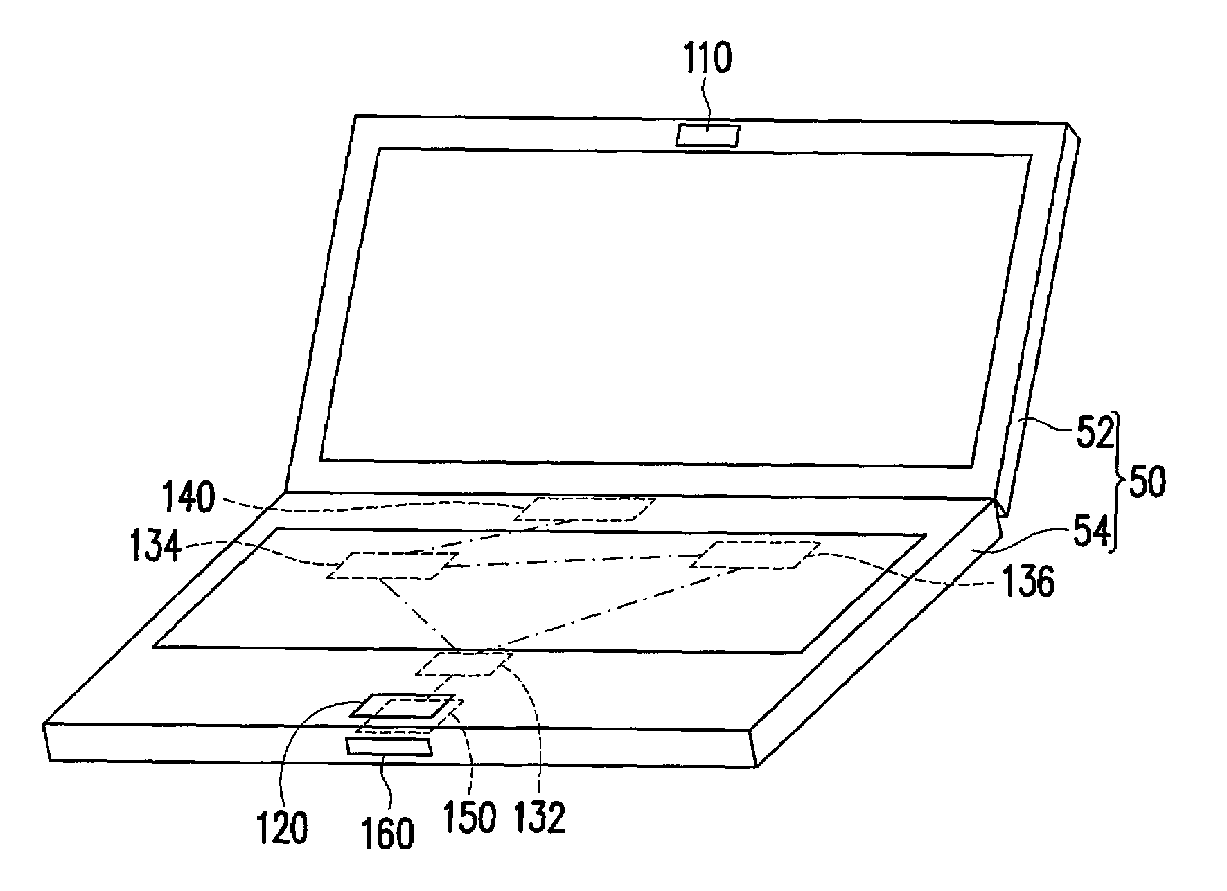
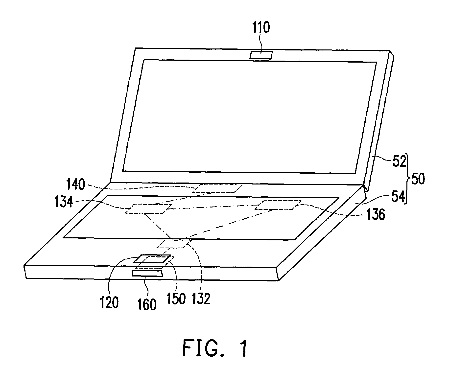
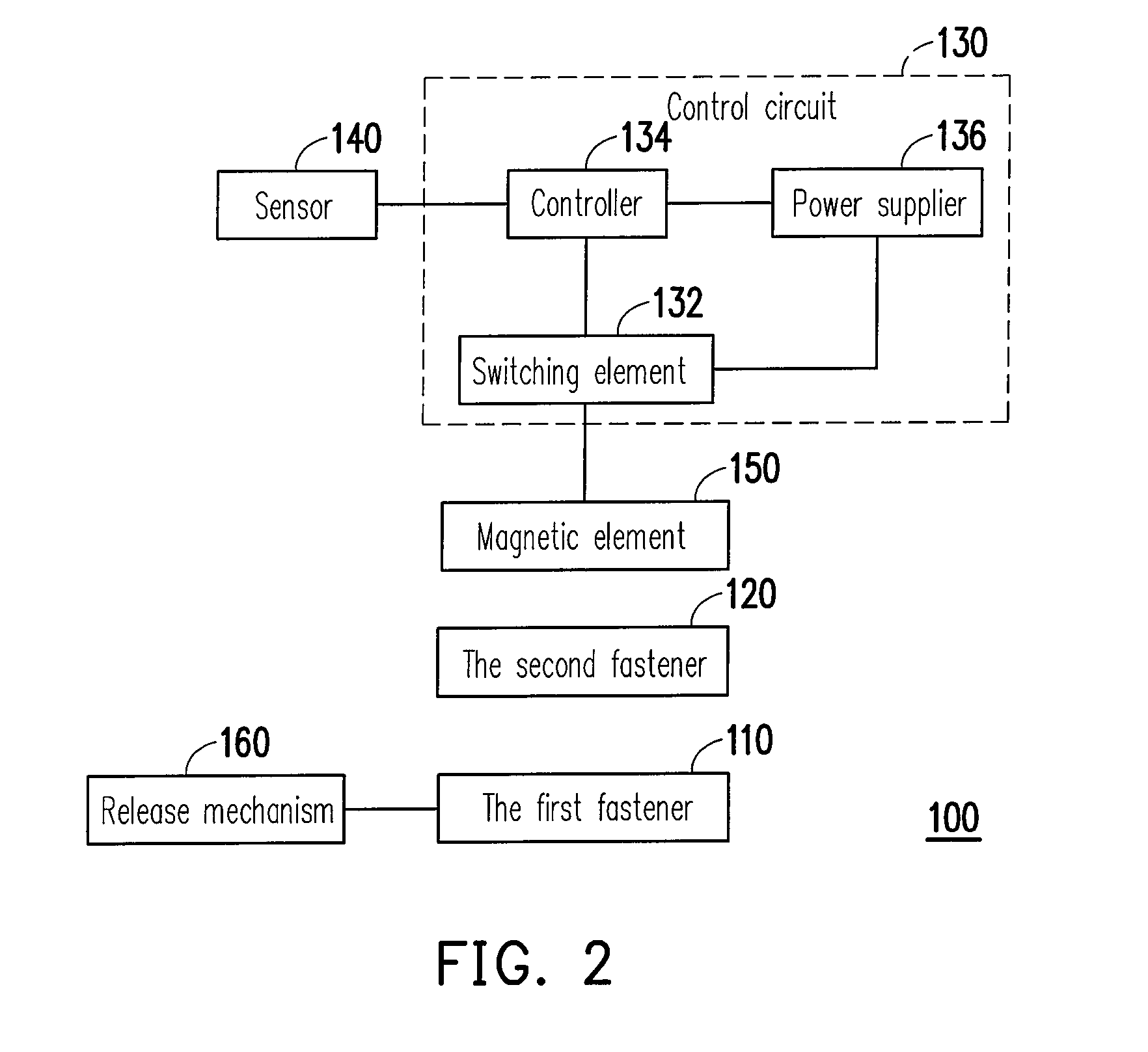
[0024]FIG. 1 illustrates a foldable electronic apparatus employing the fastener module according to an embodiment of the present invention. FIG. 2 illustrates the fastener module in FIG. 1. Referring to FIGS. 1 and 2, for example, the foldable electronic apparatus 50 in this embodiment is a notebook computer, but may also be another foldable electronic apparatus, such as a personal digital assistant or a mobile phone, so the foldable electronic apparatus 50 is not limited in the present invention at all.

[0025]The foldable electronic apparatus 50 includes a first body 52 and a second body 54 pivotally jointed with the first body 52. When the first body 52 and the second body 54 are in a closed state, in order to fix the relative position between the first body 52 and the second body 54, the foldable electronic apparatus 50 further includes a fastener module 100.

[0026]The fastener module 100 includes a first fastener 110, a second fastener 120, a control circuit 130, a sensor 140, and...


PUM


Abstract

A fastener module suitable for a foldable electronic apparatus with a first body and a second body pivotally jointed with each other is provided. The module includes a first fastener, a second fastener, a control circuit, and a magnetic element. The first fastener is disposed in the first body and has magnetic susceptibility. The second fastener is disposed in the second body and suitable for being fastened with the first fastener. The control circuit is disposed in the foldable electronic apparatus. The magnetic element is disposed in the foldable electronic apparatus, and is coupled to the control circuit. The magnetic element is controlled by the control circuit to determine whether to exert a magnetic force on the first fastener for driving the first fastener to be fastened with the second fastener.

Description

CROSS-REFERENCE TO RELATED APPLICATION[0001]This application claims the priority benefit of Taiwan application serial no. 95135734, filed Sep. 27, 2006. All disclosure of the Taiwan application is incorporated herein by reference.BACKGROUND OF THE INVENTION[0002]1. Field of the Invention[0003]The present invention relates to a fastener module, and more particularly to a fastener module controlled by magnetic force applicable to a foldable electronic apparatus.[0004]2. Description of Related Art[0005]Due to the development of semiconductor elements and display technology, an electronic apparatus is gradually developed towards a trend of being small sized, multi-functional, and convenience in carry. A foldable electronic apparatus is applied widely due to its effectively reduced area. Common foldable electronic apparatuses include a personal digital assistant, a mobile phone, a notebook computer, etc.[0006]For example, a common notebook computer mainly includes two parts, i.e., a disp...

Claims


Application Information

Patent Timeline
Patent Type & Authority Patents(United States)
IPC IPC(8): H01H9/00
CPCG06F1/1616G06F1/1679G06F1/1677Y10T292/11
Inventor KUNG, SHAO-TSUSHEN, YI-HUNG
Owner COMPAL ELECTRONICS INC
Learn More