
Channelized log-periodic antenna with matched coupling

a log-period antenna and coupling technology, applied in the field of antennas, to achieve the effect of efficient couplement and increase forward gain

Active Publication Date: 2009-10-27
RGT UNIV OF CALIFORNIA
View PDF12 Cites 4 Cited by
  • Summary
  • Abstract
  • Description
  • Claims
  • Application Information

AI Technical Summary

Benefits of technology

[0014]2) An integrated, impedance transforming balun: Since the antenna has high impedance and is to be impedance matched on a substrate (such as silicon), impedance reduction is called for. Adding a boom or spine to the antenna reduces the antenna impedance and facilitates impedance matching, by making the balun shorter resulting in fewer quarter wavelength transmission lines in series.
[0016]4) In addition, a lens can be used with the channelized planar LP antenna to increase forward gain. A typical LP antenna has a main beam f-number (f / #) of approximately 0.7. The use of a silicon elliptical lens slows the feed antenna beam to f / 2. An f / 2 antenna-lens combination can efficiently couple to many clear aperture reflector dish telescopes, which also tend to be f / 2. Hence, it is an excellent candidate for a wideband quasi-optical telescope feed.

Problems solved by technology

Many wideband planar antennas are described in the literature, but one challenge is to produce an antenna that is capable of measuring two polarizations of radiation simultaneously and that can be coupled to transmission lines that are practically fabricated using, for example, lithography on a silicon substrate.

Method used


Image

  • Channelized log-periodic antenna with matched coupling
  • Channelized log-periodic antenna with matched coupling
  • Channelized log-periodic antenna with matched coupling

Examples


examples

[0059](The contents of all references referred to in these Examples is incorporated herein by reference for all purposes.)

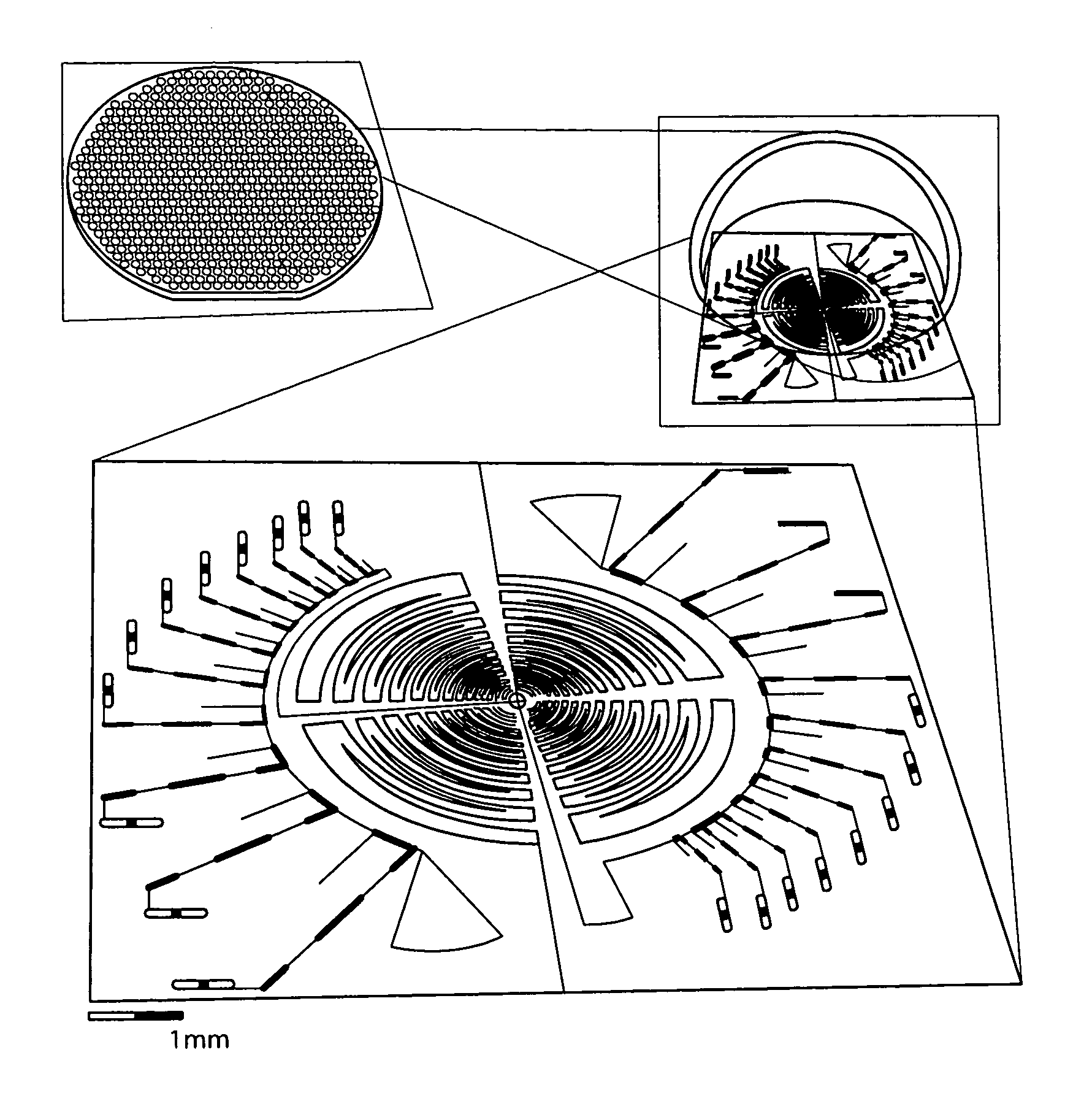
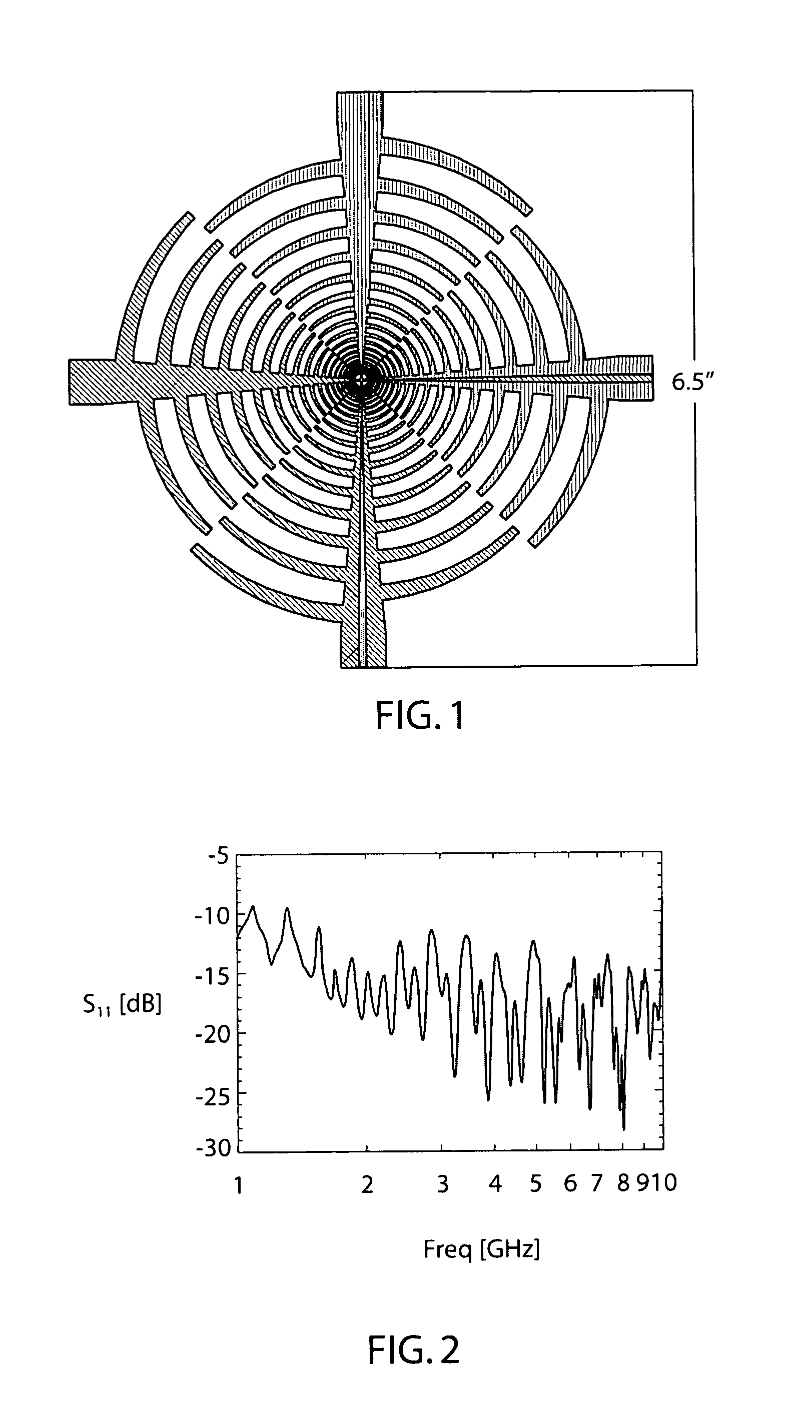
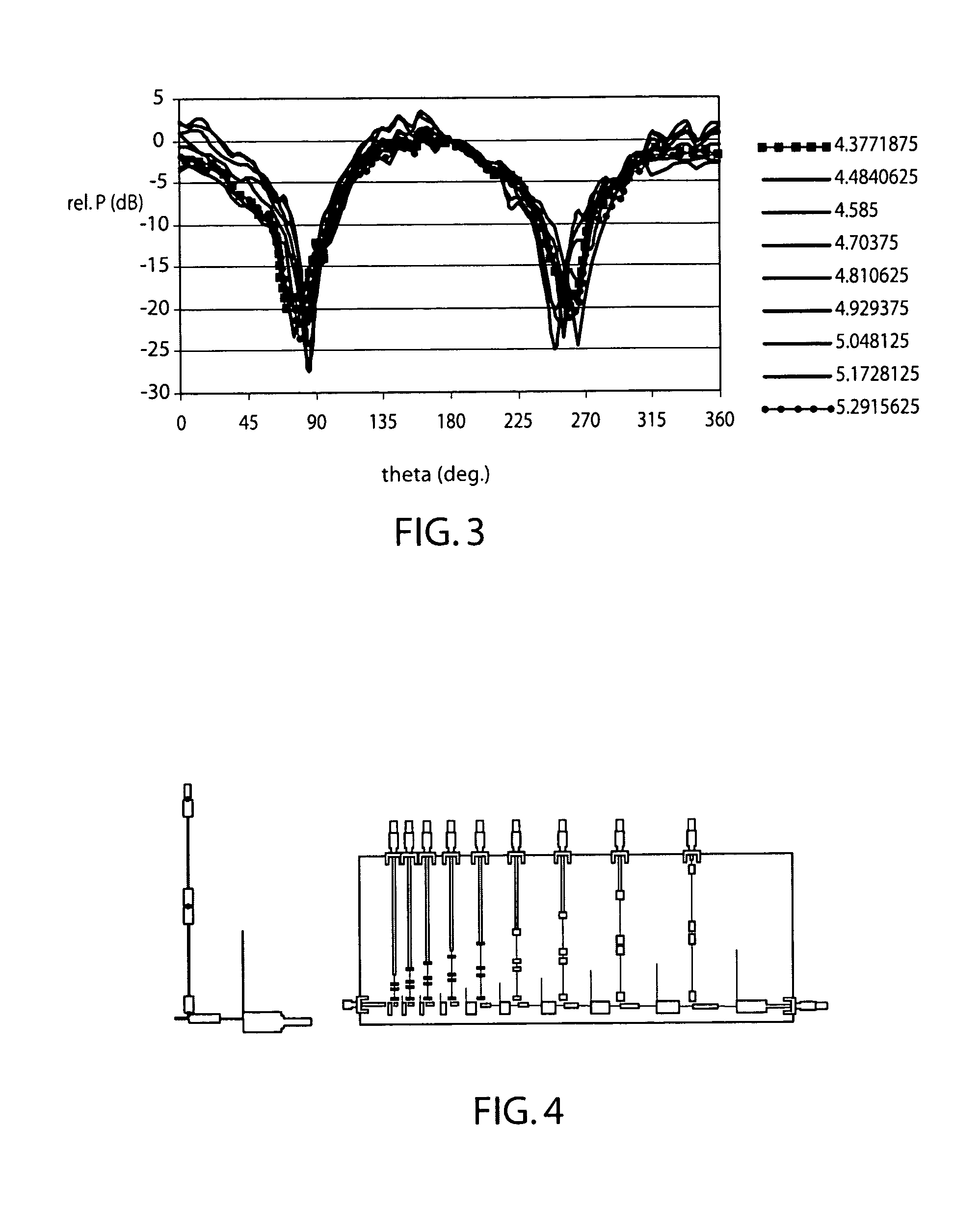
[0060]We present the design, simulation, and measurement of a dual linearly polarized log-periodic antenna matched to a log-periodic channelizing filter through a tapered microstrip balun. The design can be implemented monolithically. A prototype of the channelized antenna, which operates over 1-5 GHz, is realized on printed circuit board with a dielectric constant of 4.5. Because we designed the antenna and channelizer with the same log-period (τ=1.2) the variation in antenna impedance and radiation pattern is theoretically the same over every channel (Δν / ν˜0.2). The channel averaged radiation patterns show less variation from channel to channel (1.64-5.26 GHz) than do radiation patterns sampled over a single log-period in frequency (4.39-5.26 GHz). We are developing this channelized log-periodic antenna as a scale model of a polychromatic millimeter-wave pixel ...


PUM


Abstract

A log-periodic antenna coupled to a channelizer is described in which matched scale constants for the antenna and the channelizer are used to achieve substantially identical coupling over each fractional bandwidth channel. Embodiments for simultaneous dual polarization operation are described as well as embodiments suited for planar lithographic fabrication.

Description

CROSS REFERENCE TO RELATED APPLICATIONS[0001]This application claims priority pursuant to 35 USC § 119 from provisional patent application Ser. No. 60 / 679,264 filed May 9, 2005 the entire contents of which is incorporated herein by reference for all purposes.STATEMENT REGARDING FEDERALLY SPONSORED RESEARCH OR DEVELOPMENT[0002]This invention was made with Government support under Grant (Contract) No. AST-0096933 awarded by the National Science Foundation, and Grant (contract) No. NNG06GJ08G awarded by the National Aeronautics and Space Administration. The Government has certain rights to this invention.BACKGROUND OF THE INVENTION[0003]1. Field of Invention[0004]The present invention relates to the field of antennas and, more particularly, to channelized log-periodic antennas.[0005]2. Description of the Prior Art[0006]Astronomical observations in spectral regions ranging from approximately the far infrared (far IR) wavelengths to millimeter (mm) wavelengths are opening a new window on...

Claims


Application Information

Patent Timeline
Patent Type & Authority Patents(United States)
IPC IPC(8): H01Q11/10H01Q21/00H01Q1/50
CPCH01Q1/10H01Q19/062H01Q9/27H01Q1/38
Inventor ENGARGIOLA, GREGORYLEE, ADRIAN
Owner RGT UNIV OF CALIFORNIA
Learn More