Timestamping signal monitor device

a monitor device and signal technology, applied in the direction of generating/distributing signals, pulse characteristics measurement, instruments, etc., can solve the problems of inability to use in some environments and physical locations, complex and expensive logic analyzers,

Active Publication Date: 2009-10-27
KEYSIGHT TECH
View PDF12 Cites 57 Cited by
  • Summary
  • Abstract
  • Description
  • Claims
  • Application Information

AI Technical Summary

Problems solved by technology

Unfortunately, oscilloscopes, logic analyzers, and similar instruments are relatively complex and expensive and may not be practical to use in some environments and physical locations.

Method used


Image

  • Timestamping signal monitor device
  • Timestamping signal monitor device
  • Timestamping signal monitor device

Examples


Embodiment Construction

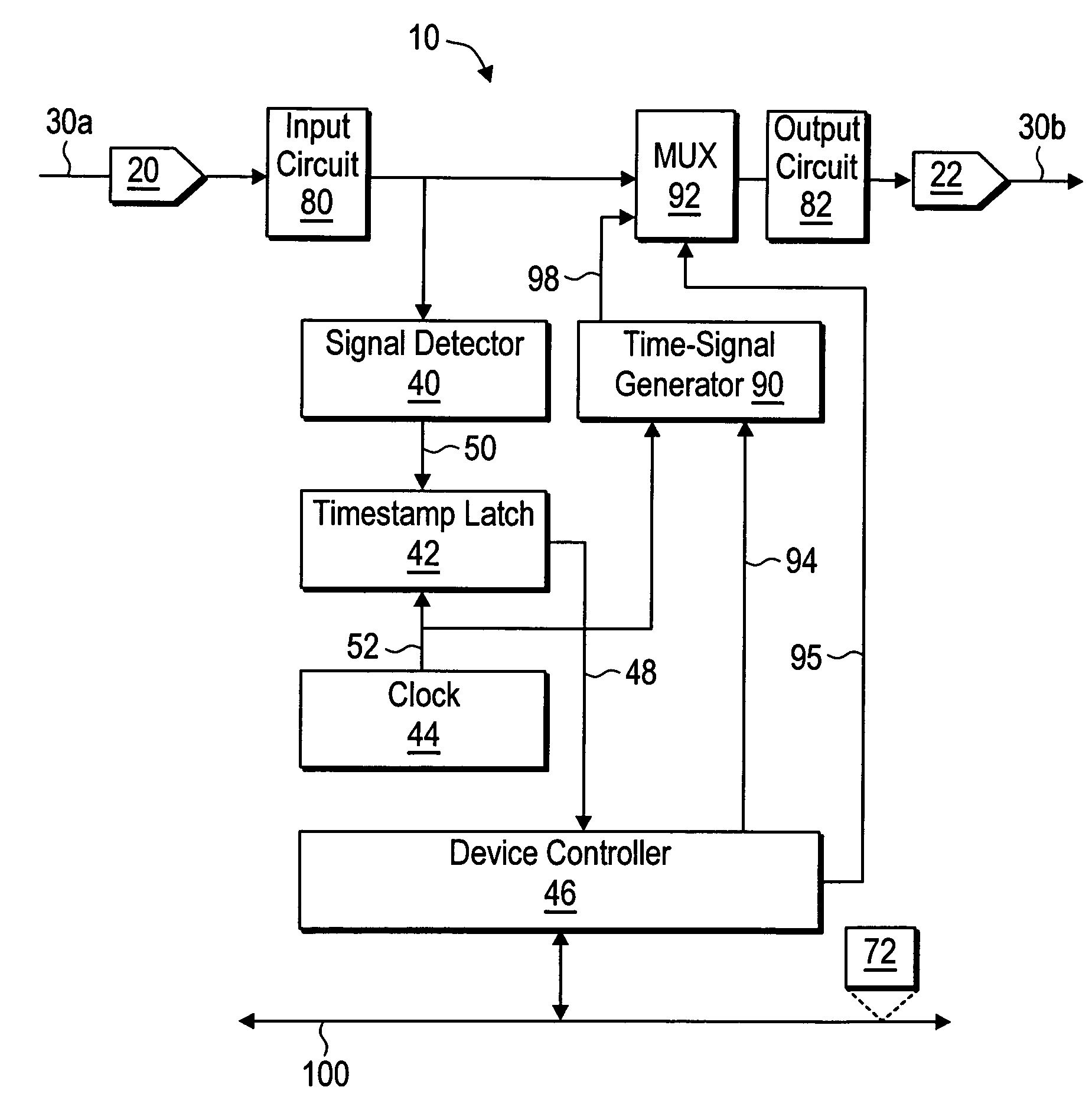
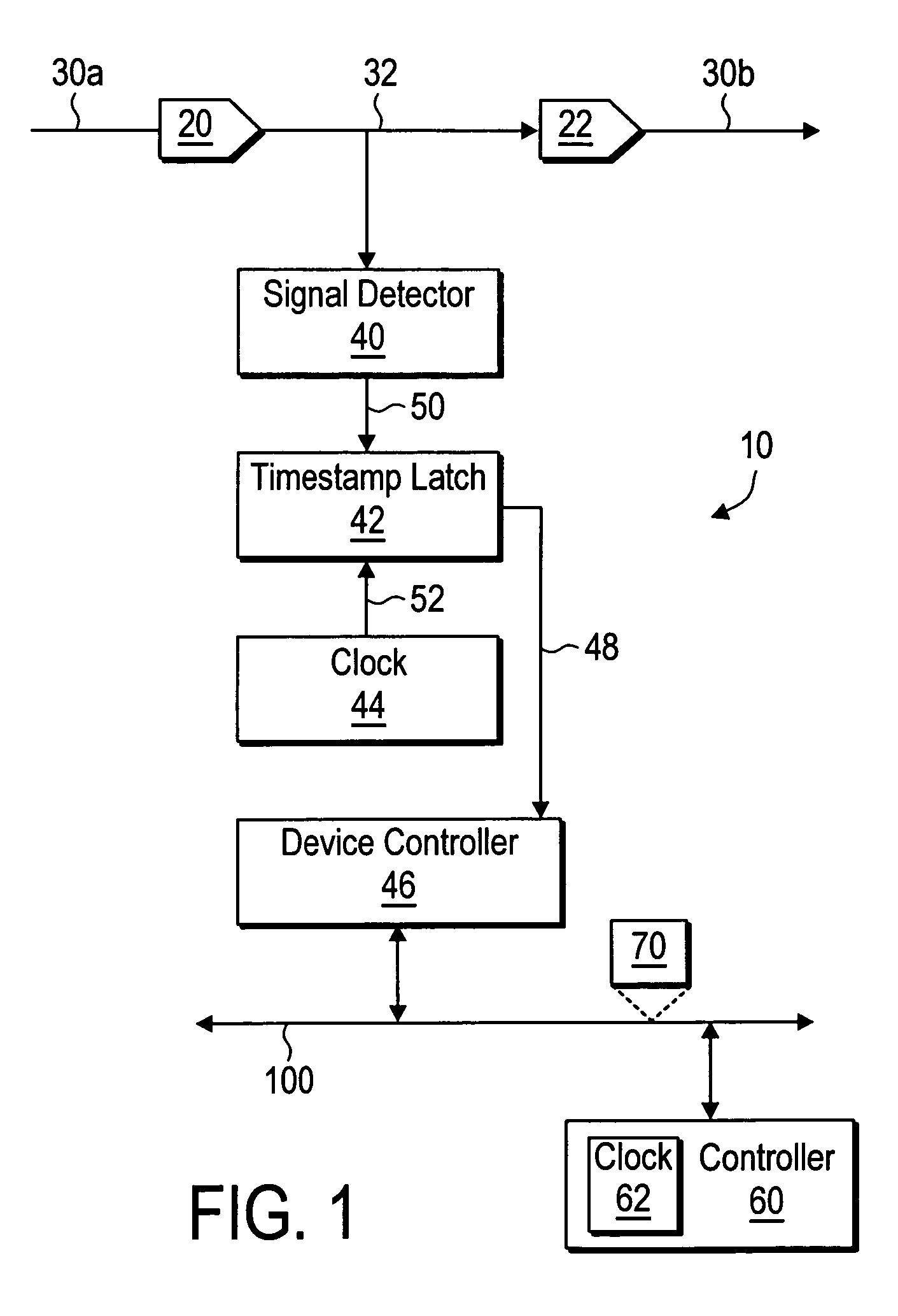
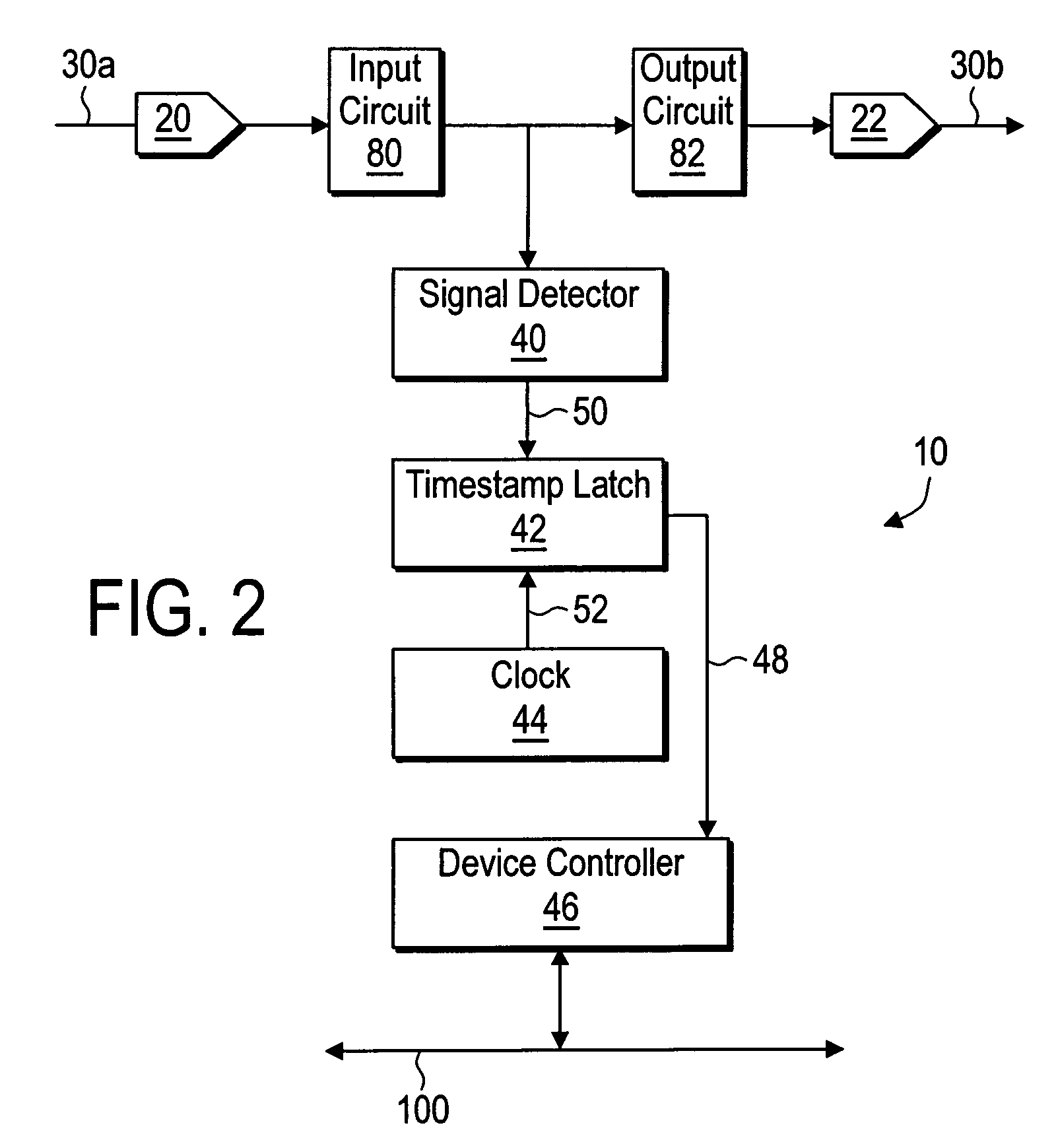
[0011]FIG. 1 shows one embodiment of a signal monitor device 10 according to the present teachings. The signal monitor device 10 includes a signal detector 40, a timestamp latch 42, a clock 44, and a device controller 46. In one embodiment, the clock 44 maintains a time-of-day. The device controller 46 includes circuitry that is adapted from communication via a network 100. The network 100 may be a wire-based network or a wireless network. The network 100 may be a local area network, e.g. Ethernet.

[0012]The signal monitor device 10 includes a pair of connectors 20 and 22 that enable the signal monitor device 10 to be inserted in the path of a signal line in between portions 30a and 30b of the signal line. The connectors 20 and 22 are adapted to the physical implementation of the signal line. For example, if the signal line is a coaxial cable then the connectors 20 and 22 are adapted for coaxial cables, e.g. BNC connections. In other embodiments, the connectors 20 and 22 may be adapt...


PUM


Abstract

A signal monitor device that detects a signal propagating on a signal line and that generates a timestamp when the signal is detected. The timestamp may be used in a variety of applications including measuring the propagation delays on signal lines and determining the timing in a system.

Description

BACKGROUND[0001]Signal lines may be used to carry a wide variety of electrical signals in a wide variety of systems. Examples of signal lines include wires, coaxial cables, twisted pairs, optical fibers, etc. Signal lines may carry analog signals, digital signals, encoded signals, data packets, etc.[0002]It may be desirable in a variety of circumstances to determine a time when an electrical signal propagating on a signal line reaches a particular point along the signal line. For example, the times when an electrical signal reaches different points along a signal line may be used to determine a propagation delay of the signal line. In another example, the times when different electrical signals in a system reach different points along different signal lines in the system may be used to determine the overall timing of the system.[0003]Oscilloscopes, logic analyzers, and similar instruments may be used to detect the presence of an electrical signal at a particular point along a signal...

Claims


Application Information

Patent Timeline
Patent Type & Authority Patents(United States)
IPC IPC(8): G06F17/40G06F19/00
CPCG01R19/2509H04J3/0685
Inventor EIDSON, JOHN C.
Owner KEYSIGHT TECH
Why Eureka
Try Eureka