Method and apparatus for a multi-gigabit ethernet architecture

a multi-gigabit ethernet and ethernet technology, applied in the field of computer systems and networks, can solve the problem of limited desire for rapid network communication

Inactive Publication Date: 2005-03-29
ORACLE INT CORP
View PDF12 Cites 81 Cited by
  • Summary
  • Abstract
  • Description
  • Claims
  • Application Information

AI Technical Summary

Benefits of technology

An Ethernet network in this embodiment comprises one or more physical links consisting of virtually any type of medium (e.g., fiber, wire). Illustratively, however, the network operates in a dedicated mode such that communications are carried in a full-duplex mode of operation only except possibly when operating at a lower commu

Problems solved by technology

In particular, because computations and operations in such a cluster are often shared or distributed among multiple end nodes, their desire for rapid netwo

Method used


Image

  • Method and apparatus for a multi-gigabit ethernet architecture
  • Method and apparatus for a multi-gigabit ethernet architecture
  • Method and apparatus for a multi-gigabit ethernet architecture

Examples


Embodiment Construction

The following description is presented to enable any person skilled in the art to make and use the invention, and is provided in the context of particular applications of the invention and their requirements. Various modifications to the disclosed embodiments will be readily apparent to those skilled in the art and the general principles defined herein may be applied to other embodiments and applications without departing from the spirit and scope of the present invention. Thus, the present invention is not intended to be limited to the embodiments shown, but is to be accorded the widest scope consistent with the principles and features disclosed herein.

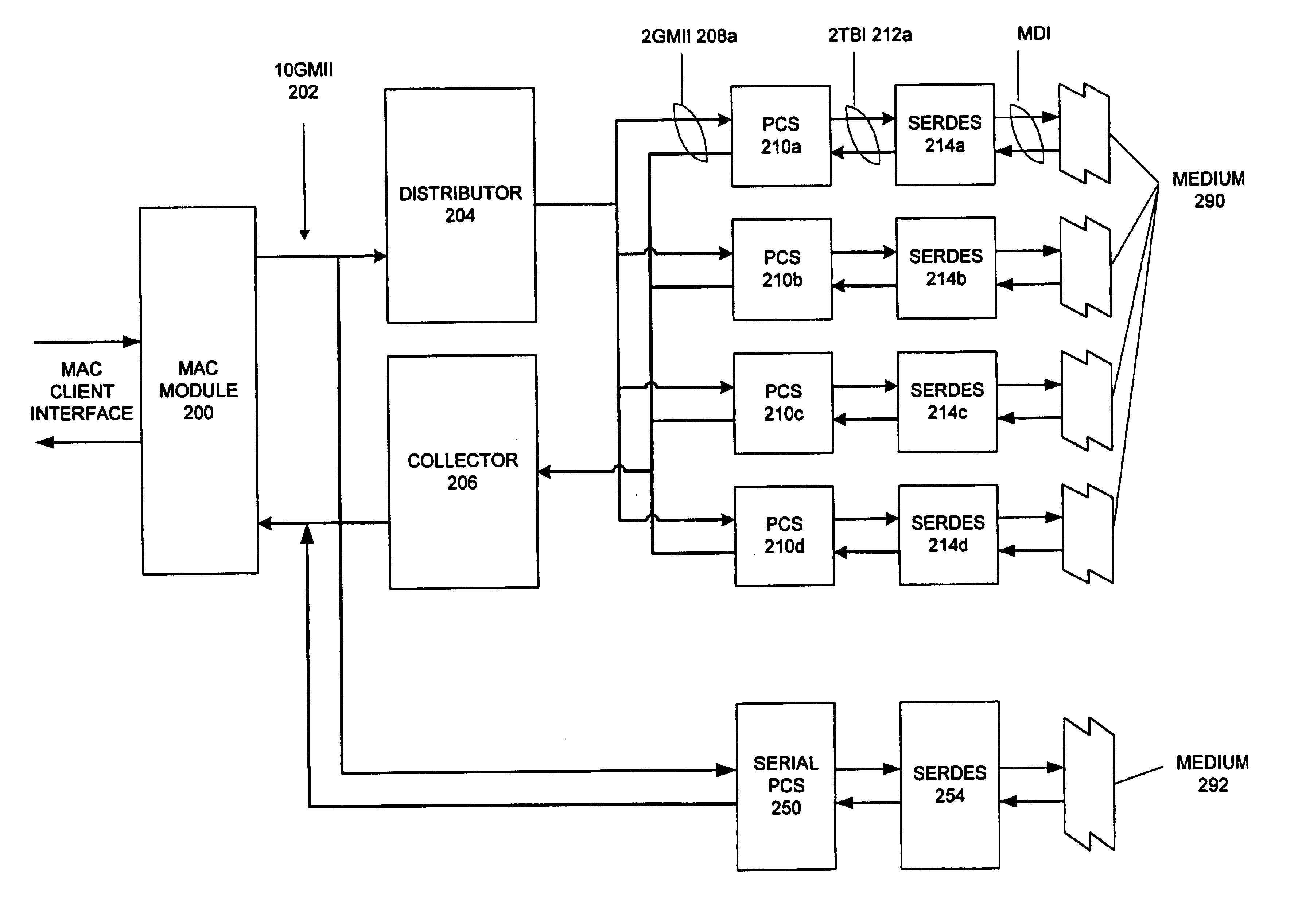
In particular, an apparatus and associated methods for implementing a high-speed Ethernet network interface is provided. Such an interface is suitable, for example, in a computer system or other communication device that is coupled to an Ethernet network. One skilled in the art will recognize that the present invention is not limited...


PUM


Abstract

An Ethernet architecture is provided for connecting a computer system or other network entity to a dedicated Ethernet network medium. The network interface enables the transmission and receipt of data by striping individual Ethernet frames across a plurality of logical channels and may thus operate at substantially the sum of the individual channel rates. Each channel may be conveyed by a separate conductor (e.g., in a bundle) or the channels may be carried simultaneously on a shared medium (e.g., an electrical or optical conductor that employs a form of multiplexing). On a sending station, a distributor within the sender's network interface receives Ethernet frames (e.g., from a MAC) and distributes frame bytes in a round-robin fashion on the plurality of channels. Each “mini-frame” is separately framed and encoded for transmission across its channel. On a receiving station, the receiver's network interface includes a collector for collecting the multiple mini-frames (e.g., after decoding) and reconstructing the frame's byte stream (e.g., for transfer to the receiver's MAC). The first and last bytes of each frame and mini-frame are marked for ease of recognition. Multiple unique idle symbols may be employed for transmission during inter-packet gaps to facilitate the collector's synchronization of the multiple channels and/or enhance error detection. A maximum channel skew is specified, and each received channel may be buffered with an elasticity that is proportional to the maximum skew so that significant propagation delay may be encountered between channels without disrupting communications.

Description

BACKGROUNDThis invention relates to the fields of computer systems and networks. More particularly, a method and apparatus are provided for interfacing a computer system or other device to an Ethernet network at a high rate of data transfer.Computer systems have evolved from objects of interest mainly for hobbyists and professionals into essential tools of a large portion of the population. Along with the increase both in number and capability of computer systems, the need to communicate between them also continues to grow. From early use in sharing peripheral equipment and carrying electronic mail to their use in today's distributed applications and client / server architectures, networks for carrying computer communications have rapidly evolved in size and scope.One particular network architecture, Ethernet, has remained predominant in many computing environments even while network transmission rates have increased exponentially. While a communication rate of 10 Mbps was once the ma...

Claims


Application Information

Patent Timeline
IPC IPC(8): H04L29/06H04L12/407H04L12/413H04L29/08H04L12/28H04L12/40
CPCH04L29/06H04L69/323H04L69/14H04L9/40
Inventor MULLER, SHIMONHENDEL, ARIEL
Owner ORACLE INT CORP
Why Eureka
Try Eureka