Timing advance configuration for multiple uplink component carriers

a technology of component carriers and advance configurations, applied in the field of time aligning uplink transmissions, can solve the problems of different propagation delays between the two component carriers, interference and propagation scenarios of the aggregated component carriers, and the difficulty of finding a spectrum band wide enough for the lte-advanced system

Active Publication Date: 2016-07-26
PANASONIC INTELLECTUAL PROPERTY CORP OF AMERICA
View PDF28 Cites 87 Cited by
  • Summary
  • Abstract
  • Description
  • Claims
  • Application Information

AI Technical Summary

Benefits of technology

[0288]In alternative implementation, the mobile terminal is adapted to perform a handover from a source access point to the aggregation point, and to perform a random access procedure with the aggregation access point to thereby time align the uplink component carrier of the first radio cell.

Problems solved by technology

Nowadays, the lack of radio spectrum has become a bottleneck of the development of wireless networks, and as a result it is difficult to find a spectrum band which is wide enough for the LTE-Advanced system.
This may result in interference that no transmission from a colliding user equipment can be decoded at the eNodeB, and the user equipments will restart the random access procedure after having reached maximum number of retransmission for their scheduled transmission.
Furthermore the deployment of technologies like Remote Radio Heads (RRH) as shown for example in FIG. 13 or Frequency Selective Repeaters (FSR) as shown for example in FIG. 14 will also cause different interference and propagation scenarios for the aggregated component carriers.
This leads to different propagation delays between the two component carriers.
The power control / power allocation procedure is complicated when considering simultaneous transmission of the PRACH and the PUSCH / PUCCH in one subframe, i.e. TTI.
However, there is no easy straightforward solution in said respect, since on the one hand uplink control information transmitted on PUCCH or PUSCH have a high priority in order to allow for proper system operation, whereas on the other hand PRACH should be also prioritized in order to ensure a high detection probability at the eNB in order to minimize the delay incurred by the RACH procedure.
In addition to the power control aspects, there is also a further disadvantage regarding the power amplifier that would have to deal with the simultaneous PRACH and PUSCH / PUCCH transmissions.
Due to the Guard Time, there are power fluctuations within one subframe, which are undesirable.
These power transients will add extra complexity to the implementation of the user equipment; in other words, the maximum power reduction needs to also change during one subframe in order to fulfill the EMC requirements.

Method used


Image

  • Timing advance configuration for multiple uplink component carriers
  • Timing advance configuration for multiple uplink component carriers
  • Timing advance configuration for multiple uplink component carriers

Examples


Embodiment Construction

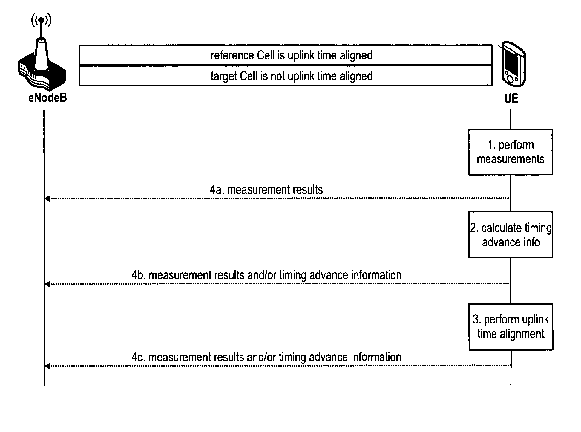
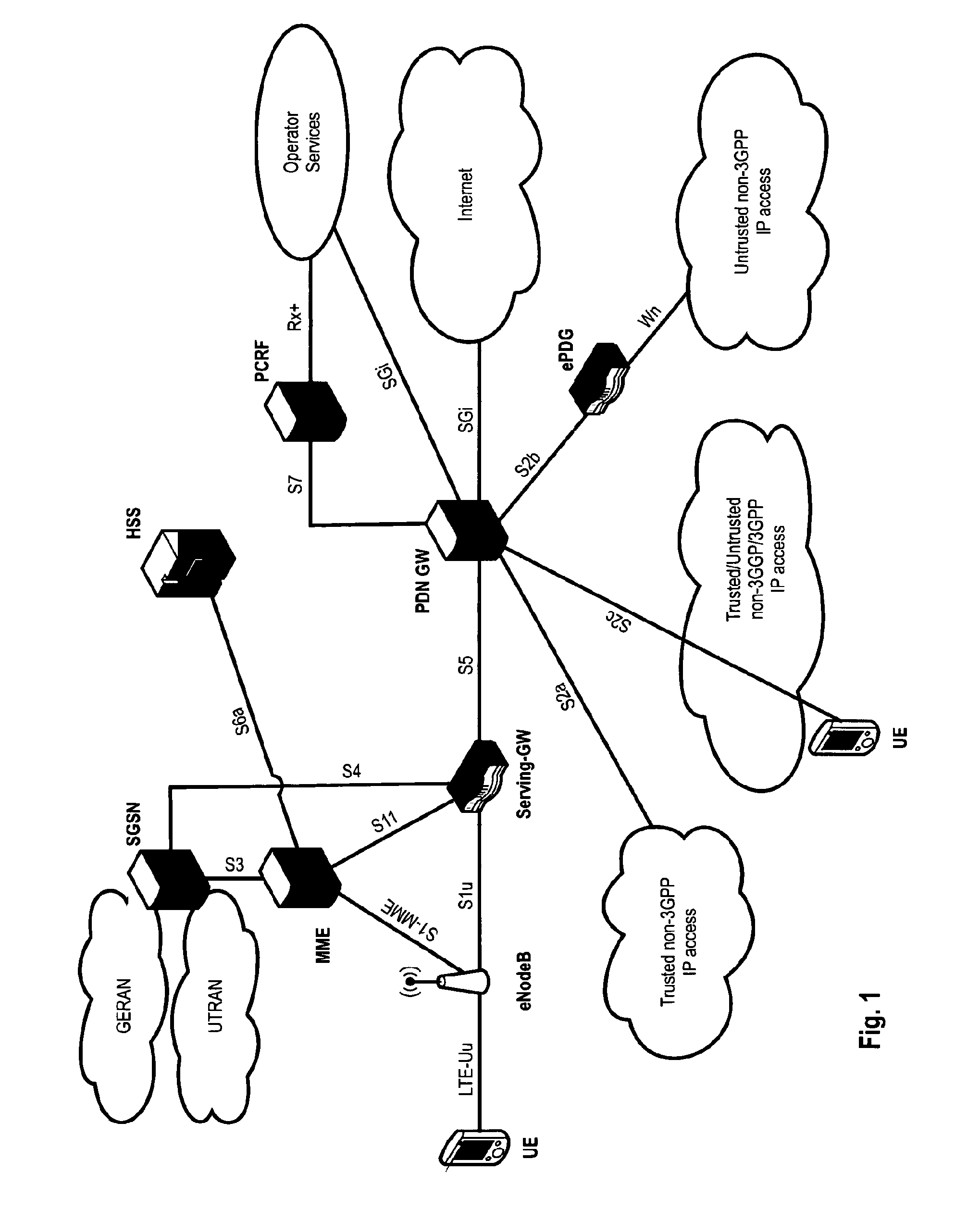
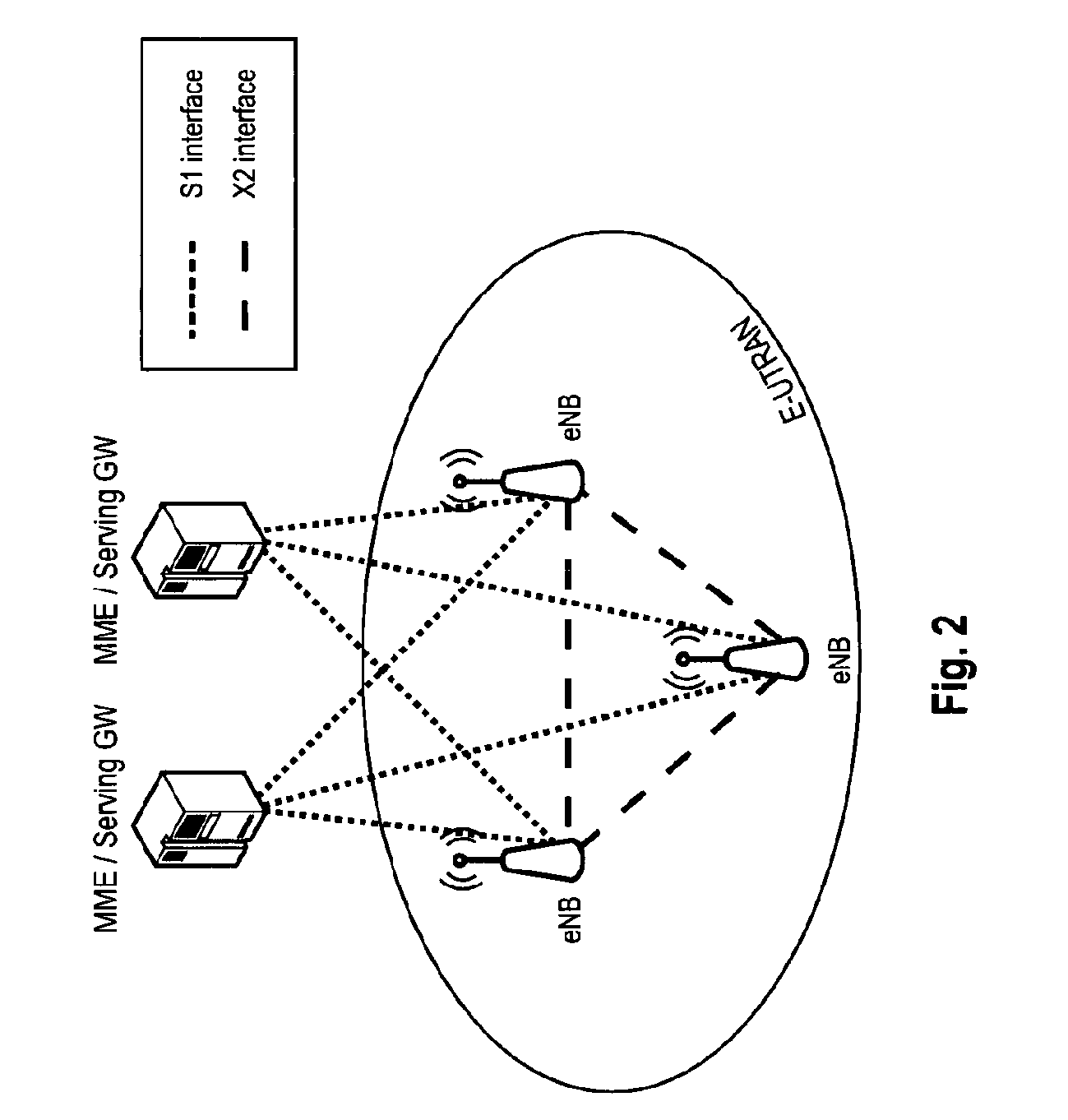
[0321]The following paragraphs will describe various embodiments of the invention. For exemplary purposes only, most of the embodiments are outlined in relation to an orthogonal single-carrier uplink radio access scheme according to 3GPP LTE (Release 8 / 9) and LTE-A (Release 10) mobile communication systems discussed in the Technical Background section above. It should be noted that the invention may be advantageously used for example in a mobile communication system such as 3GPP LTE (Release 8 / 9) and LTE-A (Release 10) communication systems as described in the Technical Background section above, but the invention is not limited to its use in this particular exemplary communication network. The invention may be broadly used in communication systems where time alignment of uplink transmissions on multiple carriers (having different propagation delays) is desired.

[0322]The explanations given in the Technical Background section above are intended to better understand the mostly 3GPP LTE...


PUM


Abstract

The invention relates methods for time aligning uplink transmissions by a mobile terminal in a mobile communication system, and to methods for performing a handover of a mobile terminal to a target aggregation access point. The invention is also providing apparatus and system for performing these methods, and computer readable media the instructions of which cause the apparatus and system to perform the methods described herein. In order to allow for aligning the timing of uplink transmissions on uplink component carriers, where different propagation delays are imposed on the transmissions on the uplink component carriers, the inventions suggests to time align the uplink component carriers based on a reference time alignment of a reference cell and a reception time difference or propagation delay difference between the downlink transmissions in the reference cell and the other radio cells, the uplink component carriers of which need to be time aligned.

Description

FIELD OF THE INVENTION[0001]The invention relates methods for time aligning uplink transmissions by a mobile terminal in a mobile communication system. The invention is also providing apparatus and system for performing the methods described herein, as well as computer readable media the instructions of which cause the apparatus and system to perform the methods described herein.TECHNICAL BACKGROUNDLong Term Evolution (LTE)[0002]Third-generation mobile systems (3G) based on WCDMA radio-access technology are being deployed on a broad scale all around the world. A first step in enhancing or evolving this technology entails introducing High-Speed Downlink Packet Access (HSDPA) and an enhanced uplink, also referred to as High Speed Uplink Packet Access (HSUPA), giving a radio-access technology that is highly competitive.[0003]In order to be prepared for further increasing user demands and to be competitive against new radio access technologies 3GPP introduced a new mobile communication ...

Claims


Application Information

Patent Timeline
Patent Type & Authority Patents(United States)
IPC IPC(8): H04W72/04H04W56/00
CPCH04W72/0446H04W56/0045H04W36/30H04W36/04
Inventor LOHR, JOACHIMWENGERTER, CHRISTIANFEUERSANGER, MARTINTAMURA, TAKASHISUZUKI, HIDETOSHIAOYAMA, TAKAHISA
Owner PANASONIC INTELLECTUAL PROPERTY CORP OF AMERICA
Why Eureka
Try Eureka