Lightweight polymer cased ammunition

a polymer cased, light-weight technology, applied in the field of ammunition articles, can solve the problems of increased weight, fatigue, heat stress, injury, performance degradation of soldiers, and army's weapons and equipment is still too heavy to allow foot soldiers to maneuver safely under fire, and achieve the effect of saving weigh

Active Publication Date: 2009-11-03
CHUNG SENGSHIN
View PDF46 Cites 318 Cited by
  • Summary
  • Abstract
  • Description
  • Claims
  • Application Information

AI Technical Summary

Benefits of technology

[0017]The bullet-end and middle body components are made of either polymer or fiber reinforced polymer composite. Injection molding of the polymer and polymer composite components maximizes the interior volume by permitting the formation of narrow-walled components. The same or different polymers can be used in the construction of the two components. Either or both components can be fiber reinforced polymer composite or un-reinforced ductile polymer. In one embodiment, the middle body component and the bullet-end component are formed from the same high temperature resistant ductile polymer.
[0018]The middle body component can have a male coupling element on both ends, in which case both the second end of the bullet-end component and the open end of the casing head-end component will have female coupling elements. The middle body component can also have a female coupling element on both ends, in which case both the second end of the bullet-end component and the open end of the casing head-end component will have male coupling elements. The middle body component can also have a male coupling element on one end and a female coupling element on the other end and the second end of the bullet-end component and the open end of the casing head-end component will have the mate for the coupling element on the end of the middle body component to which it is joined. The tips of the coupling elements may be tapered on both ends to facilitate insertion.
[0047]Accordingly, ammunition cartridge casings according to one embodiment of the present invention have a headspace length dimension that is larger than the corresponding headspace length dimension of the chamber of the intended weapon, measured at the same basic diameter for the cartridge casing at 73° F., without being so large as to jam the weapon or otherwise interfere with its action, so that at lower temperatures the headspace gap is not so large as to result in rupture of the casing. The mechanical properties of plastic compared to brass permit the use of such a design, permitting the weapon's bolt to compress the cartridge casing slightly to close the firing chamber. Cartridge casings according to this embodiment of the present invention should be between about 0.001 and about 0.030 inches larger than the corresponding chamber headspace, and preferably between about 0.002 and about 0.008 inches larger.

Problems solved by technology

Advances in weapon systems have resulted in soldiers carrying additional gear to enhance combat effectiveness, but at the cost of increased weight.
The overload causes fatigue, heat stress, injury, and performance degradation for soldiers.
Despite years of research and development, the Army's weapons and equipment is still too heavy to allow foot soldiers to maneuver safely under fire.
It is burdensome for a soldier to move around with heavy ammunition aside from carrying additional gear at the same time.
Conventional ammunition cartridge cases for rifles and machine guns, as well as larger caliber weapons, are usually made from brass, which is heavy, expensive, and potentially hazardous.
As early as 1960, the U.S. military has recognized the benefits of using polymer or polymer composite materials for cartridge case applications, and since then much research has been carried out by the military and ammunition industry, The previous studies have demonstrated feasibility but have not achieved consistent and reliable ballistic results.
To date, polymeric cartridge casings have failed to provide satisfactory ammunition with sufficient safety, ballistic and handling characteristics.
Most plastic materials, however, even with a high glass fiber loading, have much lower tensile strength and modulus than brass.
Existing polymer / composite casing technologies as a result have many shortcomings, such as insufficient ballistic performance, cracks on the case mouth, neck, body and / or base, bonding failure of metal-plastic hybrid cases, difficult extraction from the chamber, incompatibility with propellant (particularly for double base propellants), insufficient high temperature resistance (burn holes) and chamber constraints produced by thicker case walls.
Other shortcomings include the possibility of the projectile being pushed into the cartridge casing, the bullet pull being too light such that the bullet can fall out, the bullet pull being too insufficient to create sufficient chamber pressure, the bullet pull not being uniform from round to round, and portions of the cartridge casing breaking off upon firing causing weapon jam or damage or danger when subsequent rounds are fired or when the casing portions themselves become projectiles.

Method used


Image

  • Lightweight polymer cased ammunition
  • Lightweight polymer cased ammunition
  • Lightweight polymer cased ammunition

Examples


Embodiment Construction

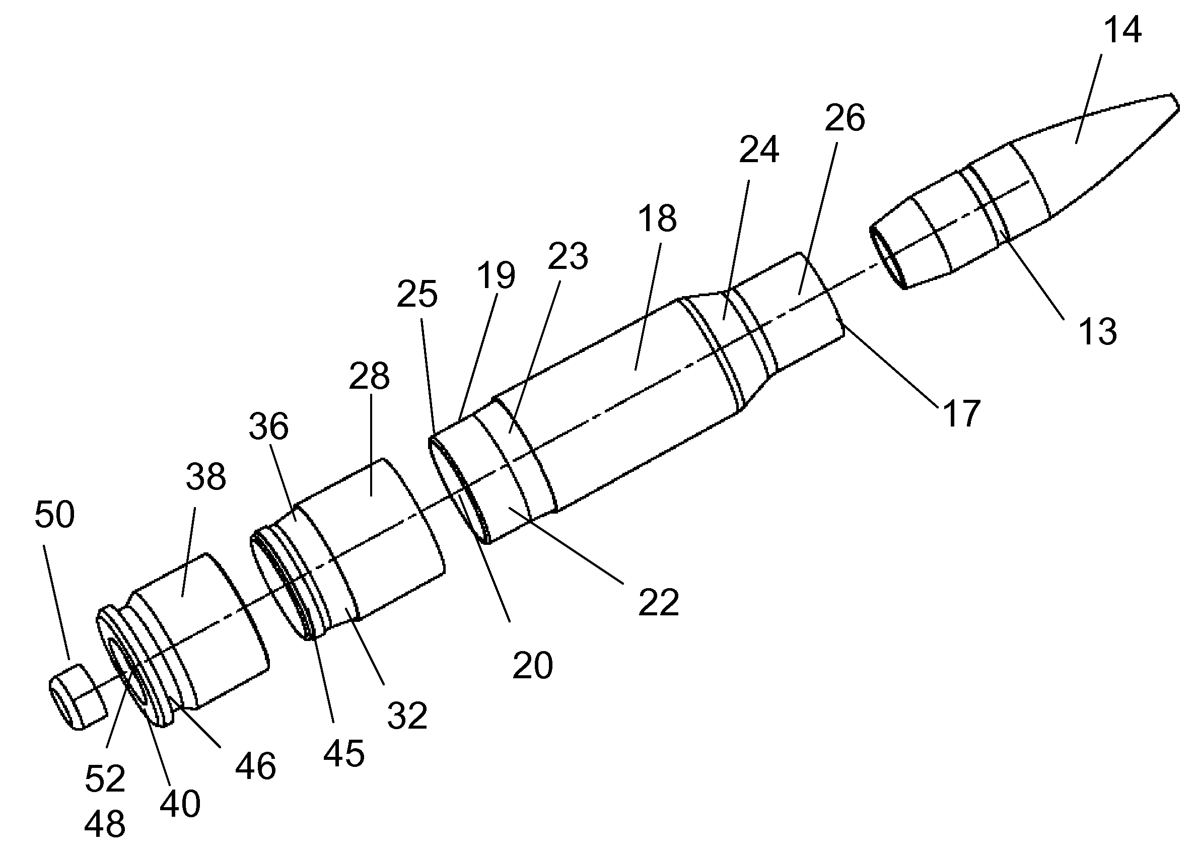
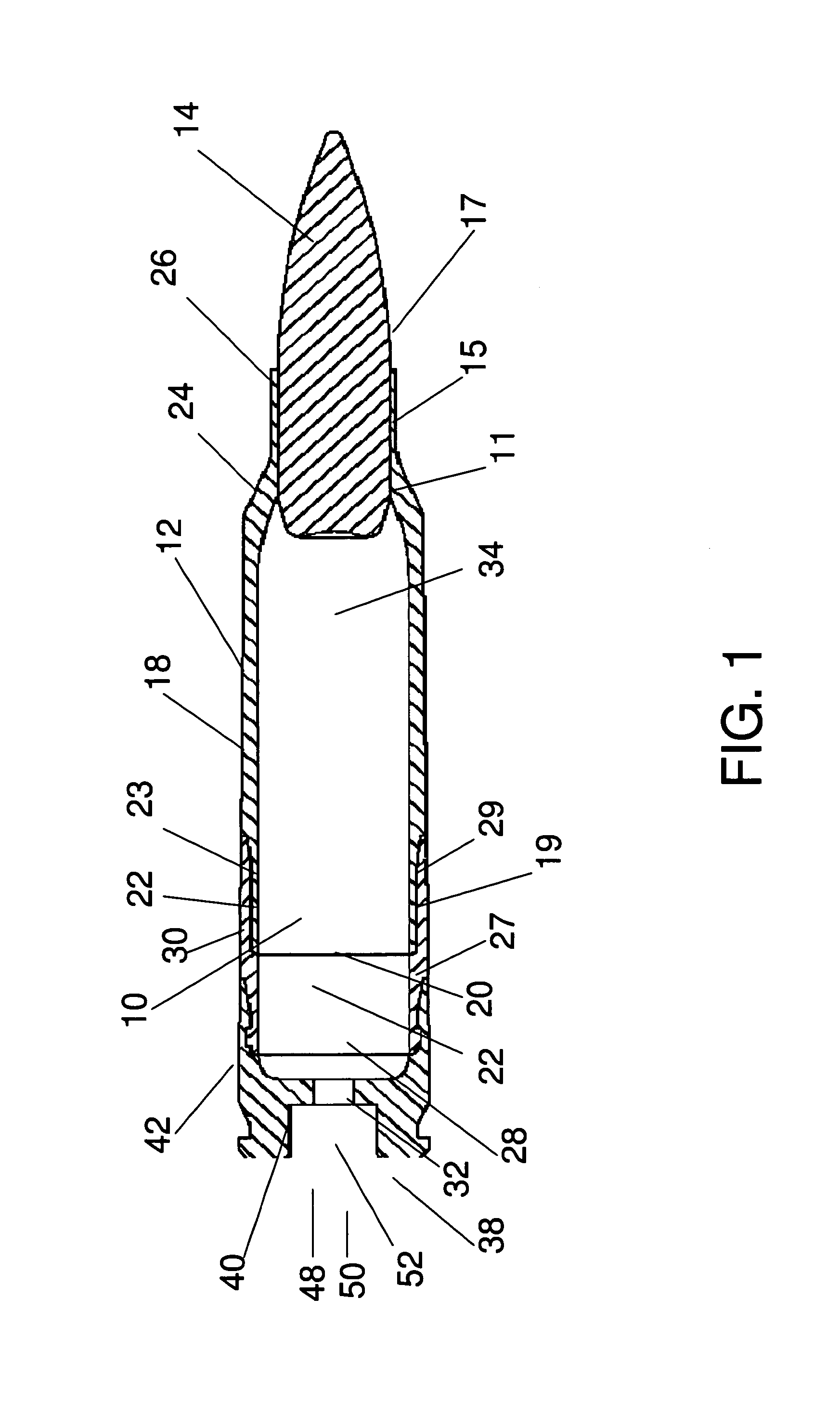
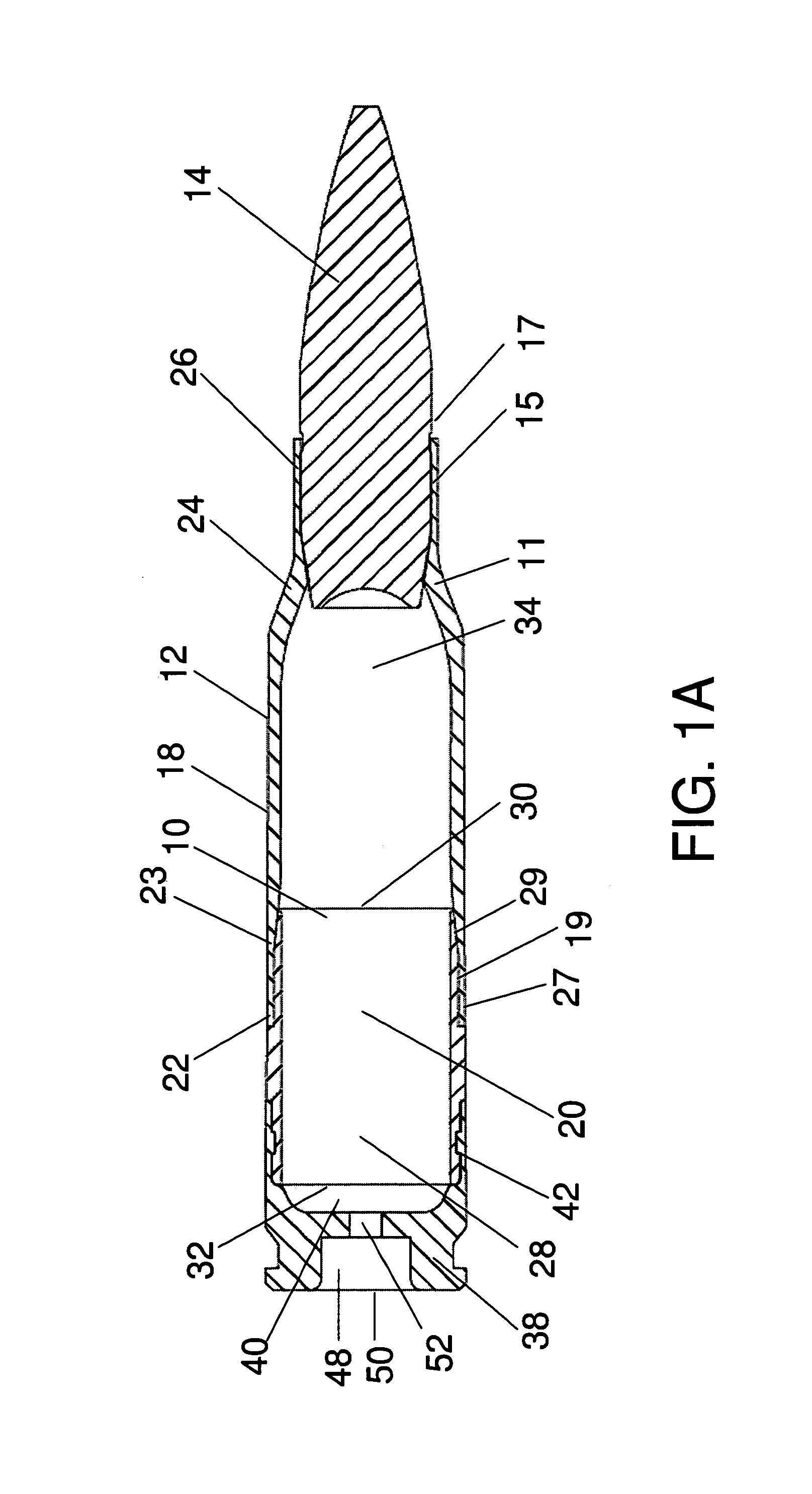
[0069]Referring particularly to the drawings, wherein like figures indicate like parts, there is depicted in FIG. 1 a side, cross-sectional view of one embodiment of the present invention. An exploded view of the same embodiment is depicted in FIG. 3. A rifle cartridge 10 suitable for use with high velocity rifles is shown manufactured with a polymer casing 12 open at both ends with projectile 14 inserted into the forward end opening 16. Polymer casing 12 has a substantially cylindrical open-ended polymeric bullet-end component 18 extending from forward end opening 16 rearward to the opposite end 20. The bullet-end component 18 is injection molded with coupling element 22 formed on end 20. Coupling element 22 is shown in FIG. 1 as a male element, but may also be configured as a female element in alternate embodiments of the invention. The forward end of bullet-end component 18 has a shoulder 24 forming chamber neck 26. The bullet-end component typically has a wall thickness between ...


PUM


Abstract

An ammunition cartridge assembled from (1) a substantially cylindrical polymeric cartridge casing body defining a casing headspace with an open projectile-end and an end opposing the projectile-end, wherein the casing body has (A) a substantially cylindrical injection molded polymeric bullet-end component with opposing first and second ends, the first end of which is the projectile-end of the casing body and the second end has a male or female coupling element; and (B) a cylindrical polymeric middle body component with opposing first and second ends, wherein the first end has a coupling element that is a mate for the projectile-end coupling element and joins the first end of the middle body component to the second end of the bullet-end component, and the second end is the end of the casing body opposite the projectile end and has a male or female coupling element; and (2) a cylindrical cartridge casing head-end component with an essentially closed base end with a primer hole opposite an open end with a coupling element that is a mate for the coupling element on the second end of the middle body and joins the second end of the middle body component to the open end of the head-end component; wherein the middle body component is formed from a material more ductile than the material head-end component is formed from but equal or less ductile than the material the bullet-end component is formed from. Methods for assembling ammunition cartridges and ammunition cartridges having the headspace length larger than the corresponding headspace length of the chamber of the intended weapon measured at the same basic diameter for the cartridge casing without being so large as to jam the weapon or otherwise interfere with its action are also disclosed.

Description

CROSS-REFERENCE TO RELATED APPLICATIONS[0001]The present application claims priority benefit of U.S. Provisional Patent Application No. 60 / 754,091 filed Dec. 27, 2005, the entire contents of all of which are hereby incorporated by reference.FIELD OF THE INVENTION[0002]The present invention relates to ammunition articles and, more particularly to ammunition articles with plastic components such as injection molded polymeric cartridge casings.BACKGROUND OF THE INVENTION[0003]Advances in weapon systems have resulted in soldiers carrying additional gear to enhance combat effectiveness, but at the cost of increased weight. Today soldiers on combat patrols in Afghanistan typically carry 92 to 105 pounds of mission-essential equipment which includes extra ammunition, chemical protective gear and cold-weather clothing. The overload causes fatigue, heat stress, injury, and performance degradation for soldiers. To ensure that America's soldiers maintain their overwhelming combat edge into the...

Claims


Application Information

Patent Timeline
Patent Type & Authority Patents(United States)
IPC IPC(8): F42B5/307F42B5/313
CPCF42B5/313
Inventor CHUNG, SENGSHIN
Owner CHUNG SENGSHIN
Why Eureka
Try Eureka