Water Turbines With Mixers And Ejectors

a water turbine and mixer technology, applied in the direction of parallel air flow wind turbines, wind turbines with perpendicular air flow, wind turbines, etc., can solve the problems of high power extraction rate, high rotor force and subsequently higher power extraction levels, and inability to use flow sensitive diffusers in many installations, etc., to achieve significant buoyancy induced vertical forces and mitigate water-borne complications

Inactive Publication Date: 2009-10-22
FLODESIGN WIND TURBINE
View PDF74 Cites 44 Cited by
  • Summary
  • Abstract
  • Description
  • Claims
  • Application Information

AI Technical Summary

Benefits of technology

[0013]The instant subject matter can provide many advantages. For example current turbines are conceptually similar to wind turbines but differ in detail in order to mitigate water-borne complications, such as: forces approximately 900 times greater than those encountered by wind turbines, significant buoyancy induced vertical forces, damaging asymmetrical/unsteady loads due to significant vertical variation in the incoming velocity field caused by the close proximity of a fixed surface such as a basin floor or wall or the hull of a ship, barge, or other waterborne craft to which the current turbine is secured. Sediment scouring can also occur fore and aft of the current turbine due

Problems solved by technology

In general, for a properly designed rotor, this increased flow speed over that of an unshrouded rotor causes more force on the rotor and subsequently higher levels of power extraction than the same size unshrouded rotor.
Diffusers, which typically include a pipe-like structure with openings along the axial length to allow slow, diffusive

Method used


Image

  • Water Turbines With Mixers And Ejectors
  • Water Turbines With Mixers And Ejectors
  • Water Turbines With Mixers And Ejectors

Examples


Embodiment Construction

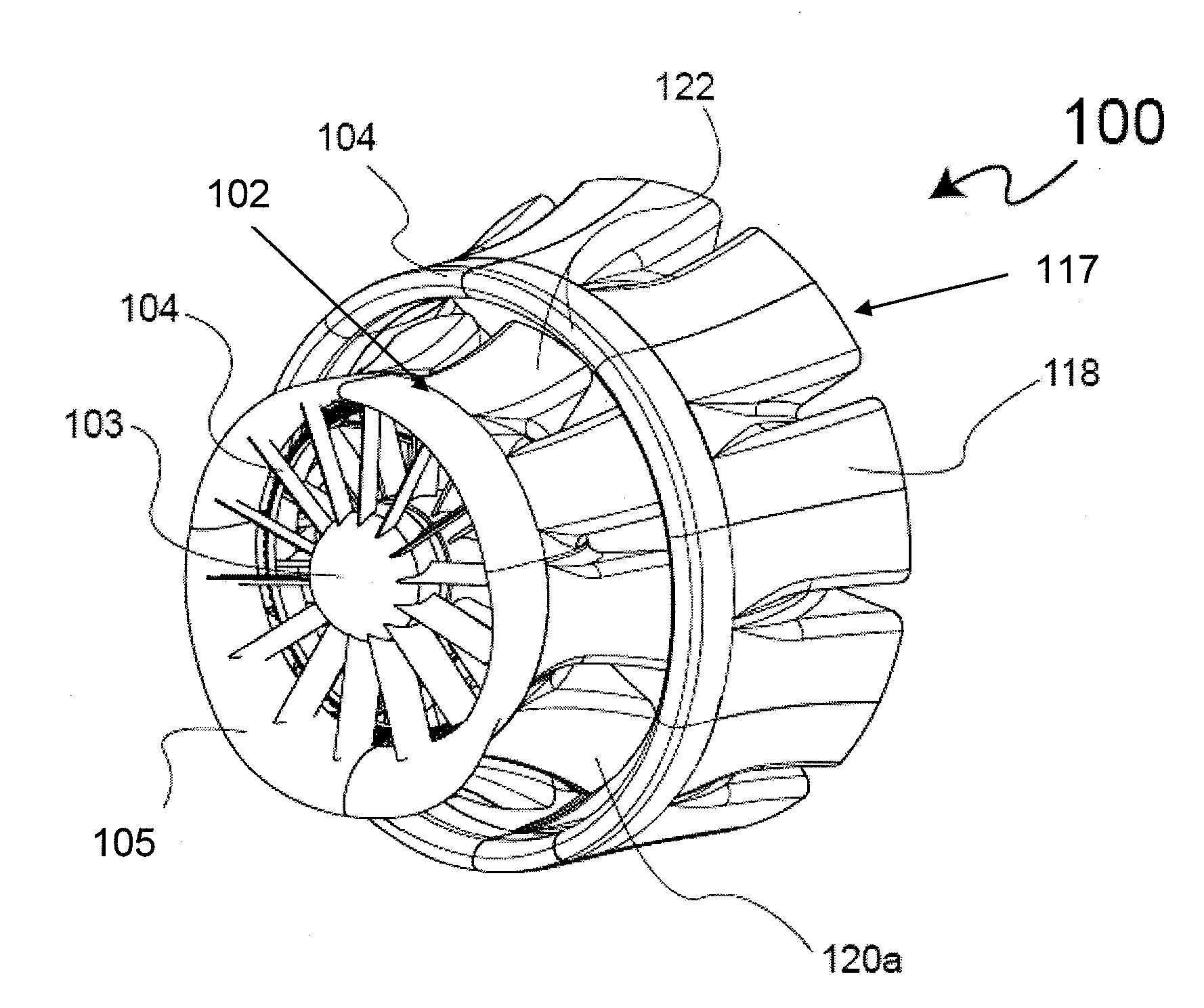
[0029]Gas turbine concepts and technology have yet to be applied commercially to axial flow current turbines. Most existing current turbines use a single multibladed rotor based on propulsive propeller concepts to extract the current energy. As a result, a significant amount of the flow passing through the current turbine blades converts some of the flow energy into swirling flow about the axis. This swirl component absorbs energy that cannot be delivered to the generator plus it induces flow rotation in the wake of the system that can induce current bed scouring, sediment stirring and aquatic life disorientation. These effects can be mitigated and even eliminated using mature gas turbine stator / rotor turbine aero / hydrodynamic flow considerations. Gas turbine rotor / stator design approaches can be applied to current turbines to essentially eliminate the detrimental effects of exit-flow swirl on the environment aft of the turbine.

[0030]Additionally, traditional single rotor systems, s...


PUM


Abstract

Turbine systems for extracting energy from water traveling relative to the turbine system can include a rotor assembly for extracting the energy, a turbine shroud having a turbine shroud inner volume within which at least a portion of the rotor assembly is disposed, and an ejector shroud having a ejector shroud inner volume within which at least a portion of the turbine shroud is disposed. The turbine shroud and the ejector shroud can each have a terminus comprising a plurality of turbine shroud mixer elements or ejector shroud mixer elements, respectively. One or more of the mixer elements and ejector shrouds comprise a mixer/ejector pump which increases the energy extraction potential of the turbine system. One or more of the turbine shroud mixer elements, ejector shroud mixer elements, and ejector shroud and turbine shroud inlets can be asymmetric about a plane passing through the axis of rotation of the rotor assembly. Methods, systems, apparatus and articles of manufacture relating to these features and others are also disclosed.

Description

CROSS-REFERENCE TO RELATED APPLICATION[0001]This application claims the benefit of U.S. provisional patent application Ser. No. 61 / 124,397, filed on Apr. 16, 2008 and entitled “Water Turbines with Mixers and Ejectors,” This application is also a continuation-in-part of co-pending application for U.S. patent Ser. No. 12 / 053,695, filed on Mar. 24, 2008 and entitled “Propeller Propulsion Systems Using Mixer Ejectors” which claims the benefit of and incorporates by reference U.S. provisional patent application Ser. No. 60 / 919,588, filed on Mar. 23, 2007 and entitled, “Mixer-Ejector Power / Propulsion System.” The disclosures of the applications from which the current applications derives a priority right are incorporated by reference herein in their entireties.FIELD[0002]The instant subject matter relates to axial flow turbine and ejector systems, such as for example, those used to extract energy when immersed in a flowing water stream, such as that of an ocean-current, tidal-current, riv...

Claims


Application Information

Patent Timeline
IPC IPC(8): F03B3/12
CPCF03D1/04F03D1/0666F05B2220/7066F05B2220/7068Y02E10/725F05B2240/97F05B2250/182Y02E10/721F05B2240/133Y02E10/72Y02P70/50F03D1/0658F03B3/04
Inventor PRESZ, JR., WALTER M.WERLE, MICHAEL J.
Owner FLODESIGN WIND TURBINE
Why Eureka
Try Eureka