Vibration isolating pipe clip

Inactive Publication Date: 2009-11-03
J VAN WALRAVEN
View PDF11 Cites 7 Cited by
  • Summary
  • Abstract
  • Description
  • Claims
  • Application Information

AI Technical Summary

Benefits of technology

[0014]By using porous vulcanized rubber instead of solid rubber or foamed rubber, as known from the prior art, it is possible to make optimum use of the advantageous properties of solid rubber —in particular with regard to the elastic deformability properties—while moreover obtaining the desired “soft behaviour” of the vibration isolating member as a result of the porosity.
[0016]In the case of pipe clips in which the rigid, substantially annular pipe clip body lies around the outside of the substantially annular vibration isolating member, in practice this bulge can only form in the lateral direction (in the direction of the axis of the pipe). The known shapes of the vibration isolating member with internal passages and / or external fins and grooves are intended to promote this mechanism of local compression under the influence of the pipe and lateral bulging and in this way to facilitate the compression of the vibration isolating member.
[0019]On account of porous elastomer material, preferably porous vulcanized rubber, being used as material for the vibration isolating member for a pipe clip as proposed by the invention, it is possible to obtain a much larger free surface area than in the case of the known vibration isolating members for pipe clips, since the cavities make a considerable contribution to the free surface area. In this way, it is possible to obtain a significantly lower form factor than with the known vibration isolating members for pipe clips. As a result, it is possible to obtain a pipe clip with noticeably favourable isolating properties without the external dimensions of the vibration isolating member (and therefore of the pipe clip) having to be altered compared to the known pipe clips.
[0020]The free surface area of the porous material created by the cavities is also advantageous for the vibration isolating effect if the shear load of the vibration isolating member is taken into account, since a vibrating pipe also exerts dynamic forces on the vibration isolating member in the longitudinal direction of the pipe, leading to shearing of the said isolation member. Compared to solid rubber, the active surface which is subject to shear in the case of the vibration isolating member according to the invention is significantly smaller and therefore the vibration isolating member provides less shearing resistance. This too makes a considerable contribution to the isolating properties of the pipe clip according to the invention.

Problems solved by technology

A drawback of these known pipe clips is that the cell walls of film thickness are only able to withstand a very low repeated load and buckle in the event of this load being exceeded meaning that they have then permanently collapsed.
Even an excessive static load may cause the cell walls to rupture.
This means that foam rubbers are in the long term insufficiently stable for this application, and moreover such materials are undesirably sensitive to temperature.
In practice, pipe clips with a foam rubber vibration isolating member are only suitable for relatively undemanding applications under light loads.
This effect is important, for example, in the case of medium-carrying lines, such as water pipes, central heating pipes and the like in buildings, in which context the transmission of vibrations from these lines to the walls and ceilings to which the lines are secured using the pipe clip constitutes a problem.
A producer is known where the latter value is higher by a factor of 5 than the former value It will be clear that such a great difference means that a very large number of pipe clips are required to support a pipe, leading to undesirably high levels of difficulty in installation.
Another drawback of a low maximum working load for retaining vibration isolation is that in practice there is a considerable risk of the vibration isolating member in fact being subject to heavier loads than the static working load calculated when designing the installation.
If one pipe clip is aligned slightly inaccurately with respect to the pipe, which in practice is almost inevitable, this will result in an additional load on the vibration isolating member.
Also, in practice there is a considerable risk of the annular clip body of the pipe clip being tightened excessively around the pipe, in particular now that use is often made of powerful electric screwdrivers to tighten the bolt(s) of the pipe clip.
(Excessive) tightening of the pipe clip also leads to an additional static load on the vibration isolating member.
These effects cause the vibration isolating effect to decrease or be lost altogether.
Hitherto, these effects have not been taken into account when assessing the vibration isolating effect of the pipe clips by means of laboratory-scale tests.

Method used


Image

  • Vibration isolating pipe clip
  • Vibration isolating pipe clip
  • Vibration isolating pipe clip

Examples


Embodiment Construction

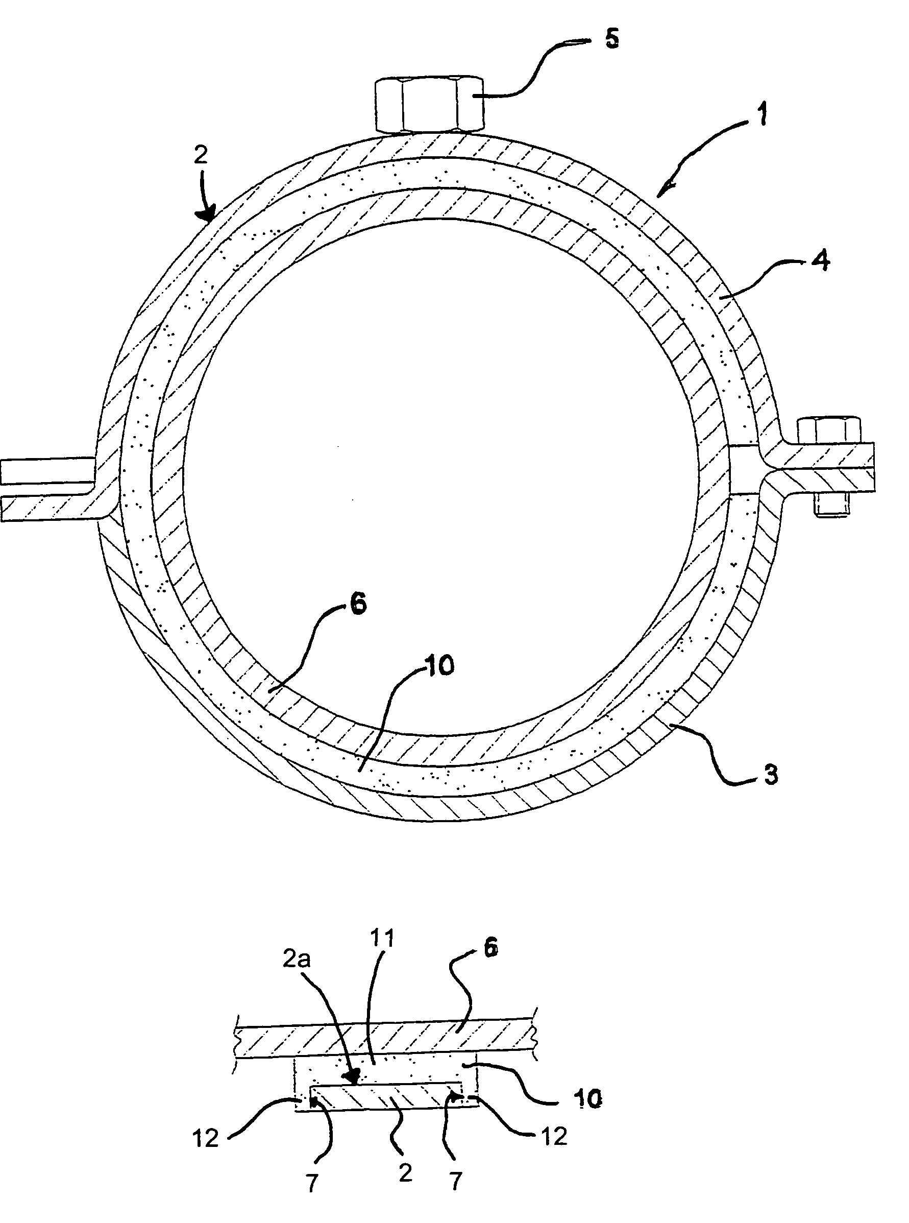
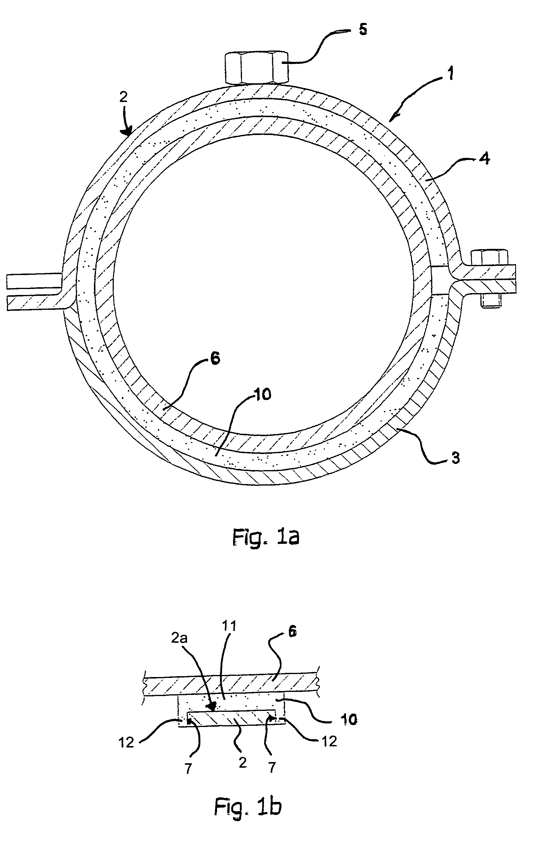
[0049]FIGS. 1a and 1b diagrammatically depict a cross section through a vibration isolating pipe clip 1 according to the invention for securing a pipe 6 to a support, in particular for securing a medium-carrying pipe 6 to a wall or ceiling of a building.

[0050]The pipe clip 1 has a substantially rigid annular pipe clip body 2 which is composed of a first clip half 3 and a second clip half 4 and is provided with securing means, in this example nut 5, for securing the pipe clip body to a support.

[0051]It will be clear that the term annular does not mean that the pipe clip body 2 is circular in shape, for example it is also conceivable for the pipe clip body 2 to be of square or polygonal design.

[0052]Furthermore, the pipe clip 1 has a substantially annular vibration isolating member 10 which bears against the inner circumference 2a of the pipe clip body 2 and during assembly is ultimately positioned between the outer circumference of the pipe 6 and the pipe clip body 2. In this example...


PUM


Abstract

A vibration isolation pipe clip for securing a pipe to a support, in particular for securing a medium-carrying pipe to a wall or ceiling of a building.The pipe clip has a substantially annular, rigid pipe clip body which is composed of one or more parts and is provided with a securing element for securing the pipe clip body to a support.A substantially annular vibration isolating member is provided, this vibration isolating member bearing against the inner circumference of the pipe clip body and ultimately being positioned between the outer circumference of the pipe and the pipe clip body.The vibration isolating member is made from a porous elastomer material, preferably vulcanized porous rubber with closed cavities and separating walls between them.

Description

BACKGROUND OF THE INVENTION[0001]The invention relates to a vibration isolating pipe clip for the vibration isolating securing of a pipe to a support, in particular a wall or ceiling of a building.[0002]The invention relates in particular to the vibration isolating member of a pipe clip of this type, which vibration isolating member is located between the pipe and the pipe clip body. The vibration isolating member is intended to reduce the transmission of vibrations from the pipe to the pipe clip body and then to the support.PRIOR ART[0003]U.S. Pat. No. 592,755 describes a large number of different vibration isolating members for a pipe clip. U.S. Pat. No. 592,755 proposes that the vibration isolating member be designed in such a manner that one or more internal passages extending in the circumferential direction are present in the vibration isolating member. In addition to the solution of providing internal passages, it is also known to arrange grooves and fins at the inner circumf...

Claims


Application Information

Patent Timeline
IPC IPC(8): F16L3/08F16L55/035
CPCF16L55/035
Inventor VAN WALRAVEN, JAN
Owner J VAN WALRAVEN
Why Eureka
Try Eureka