Optical recording medium

Inactive Publication Date: 2005-10-06
TDK CORPARATION
View PDF4 Cites 12 Cited by
  • Summary
  • Abstract
  • Description
  • Claims
  • Application Information

AI Technical Summary

Benefits of technology

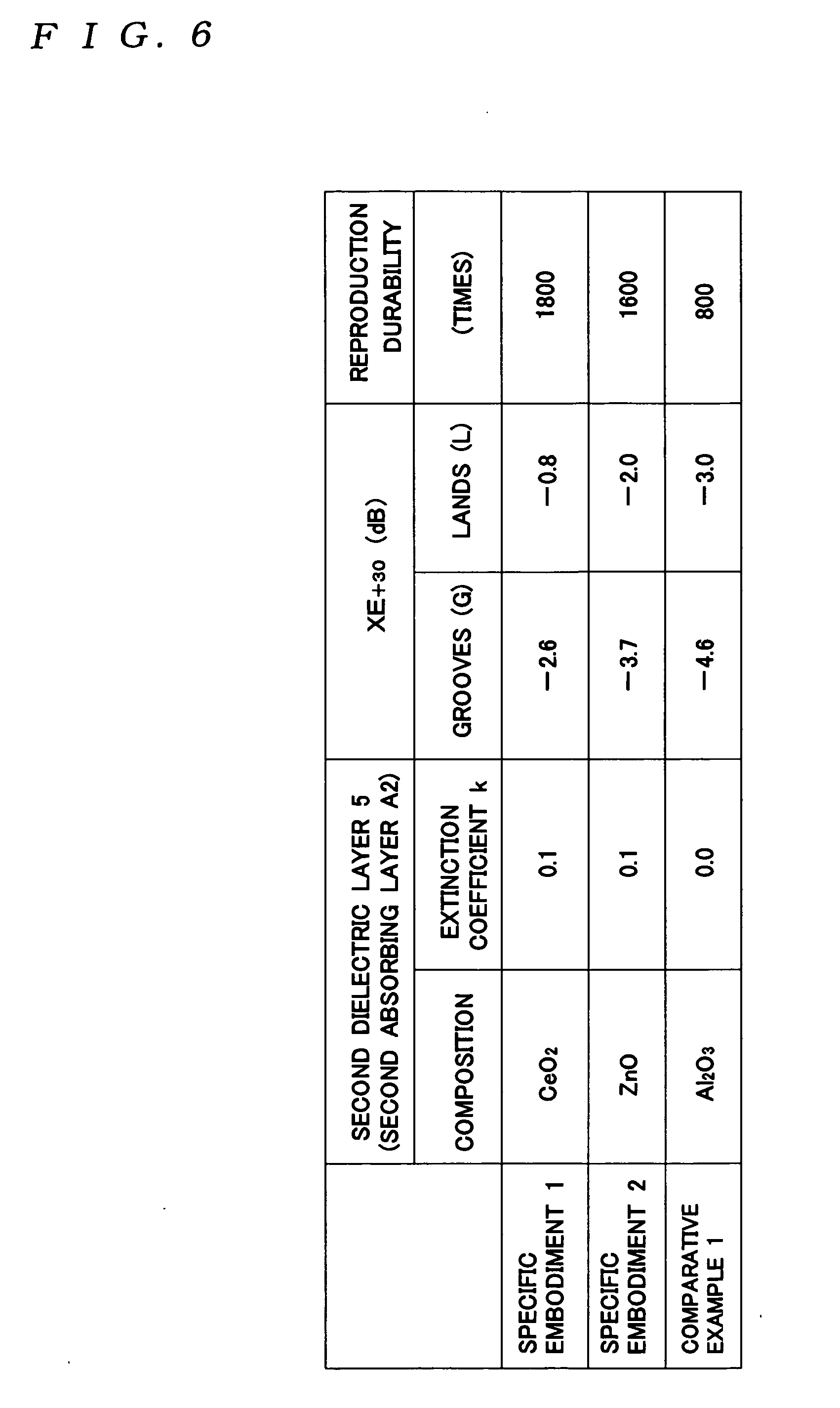
[0037] In this case, as described for specific embodiments given later, although the effect of the present invention can be realized by providing absorbing layers A made of ZnO (whose extinction coefficient k=0.1), the effect of the invention is not realized when a ZnO target is used and reactive sputtering is conducted in an atmosphere including oxygen gas to form the absorbing layers A (whose extinction coefficient k=0). That is, even if the composite elements of the absorbing layers A are the same, by varying the ratio of the composite elements, a small variation is caused in the extinction coefficient k from 0.1 to 0, which prevents the effect of the invention from being realized. Accordingly, to stably realize the effect of the invention, it is necessary to strictly control the formation of the absorbing layers A so that the intended value is achieved for the extinction coefficient k. More specifically, when the absorbing layers A are formed by sputtering, for example, the extinction coefficient k is controlled via the target composition, the flow of the reactive gas during reactive sputtering, and the like.
[0038] To sufficiently achieve the effect of the invention, it is also preferable to form the absorbing layers A so as to tightly adhere to the recording layer 4. However, it is possible to provide other layers (such as dielectric layers aside from the first dielectric layer 3 and the second dielectric layer 5) between the recording layer 4 and the absorbing layers A. However, when the layers formed between the recording layer 4 and the absorbing layers A are too thick, there is the risk of the effect of the invention being lost, so that the thickness of such layers is set at 30 nm or below, and preferably at 20 nm or below. In addition, although the present invention is especially effective for phase-change optical recording media, the invention can also be applied to optical recording media (such as magneto-optical recording media) that use heat mode recording. With such magneto-optical recording media, normally when λ / NA is small, magnetic inversion due to repeated reproduction can easily occur, as can cross-erasing. However, by using the multilayer structure according to the present invention, such problems can be effectively avoided.
[0039] Japanese Laid-Open Patent Publication No. S63-217542 discloses an optical information recording member where transparent heat-resistant protective layers are formed so as to sandwich the recording layer and second heat-resistant protective layers that exhibit absorption at the wavelength of the laser light L used for recording and erasing are also formed between the recording layer and the heat-resistant protective layers. The second heat-resistant protective layers disclosed in this publication are similar to the absorbing layers A for the present invention in exhibiting absorption at the wavelength of the laser light L. However, as described below, the present invention is very different to the invention of this publication.
[0040] In the “Effects” section of the publication, it is stated that by using protective layers that absorb light, the thickness of the light absorbing layers (the recording layer and the protective layers) is larger than in conventional media, resulting in an increase in heat capacity, so that it is possible to make a temperature distribution in the track width direction within the recording track grooves uniform. That is, in the invention disclosed by the publication, as shown by the curve 10 in FIG. 2 of the publication, the region in which the temperature rises due to irradiation with the recording light extends in the width direction for recording tracks and the peak temperature in the center of the recording tracks falls. Accordingly, from the disclosure of the publication, when protective layers that absorb light are provided, no reduction in cross-erasing will occur, and conversely an increase in cross-erasing is expected. However, when the present inventors conducted experiments for the disclosure of the publication, the unexpected effect of a reduction in cross-erasing was observed.
[0041] Here, the invention disclosed by the publication differs from the first aspect of the present invention in that no heat sink layer that favorably dissipates heat is provided. Accordingly, in the invention of the publication, since no heat sink layer is provided, the generated heat will accumulate in the protective layers that absorb light, so that as a result, it is thought that the region of the recording layer with raised temperature will extend in the width direction of the recording track to cause cross-erasing. However, for the invention of the publication, recording is carried out using laser light with a wavelength of 830 nm and compared to the first aspect of the present invention, the beam spot diameter is large, so that the energy density inside the beam spot is comparatively low. For this reason, with the invention of the publication, it is thought that there will be no particular problems relating to cross-erasing and reproduction durability. Accordingly, if short recording marks were recorded with a short-wavelength laser under the same conditions as the second aspect, it is thought that major problems would occur relating to cross-erasing and reproduction durability.
[0042] In addition, for the invention of the publication, laser light L of a remarkably long wavelength of 830 nm is used. For this reason, although no mention is made of a shortest mark length in the publication, the shortest mark length of the publication is expected to be far longer than the shortest mark length recorded on the optical recording medium according to the second aspect of the present invention. Accordingly, for the invention of the publication, it would be difficult to reduce jitter in the same conditions as the second aspect of the present invention where short recording marks are recorded using a laser with a short wavelength.

Problems solved by technology

Due to such recrystallization, there is the problem of an increase in jitter, that is, there is a large decrease in reproduction durability.
Accordingly, although it may be thought that jitter can be reduced using laser light with a large (λ / NA) value, in such case there is the problem of it being difficult to raise the recording density.
Also with a conventional optical recording medium, recrystallization or so-called “cross-erasing” occurs for recording marks (amorphous parts) formed in tracks that are adjacent to the track being recorded (hereinafter such tracks are referred to as “adjacent tracks”), and there is the problem of the C / N ratio falling due to the occurrence of such cross-erasing.
For this reason, it is thought that it will normally be difficult to avoid the occurrence of cross-erasing by changing the spot diameter of the laser beam.

Method used


Image

  • Optical recording medium
  • Optical recording medium
  • Optical recording medium

Examples


embodiments

[0061] Embodiments of an optical recording medium according to the present invention will now be described in more detail with reference to the drawings.

first embodiment

[0062] Optical recording media according to specific embodiments 1 and 2 and a comparative example 1 shown in FIG. 6 were fabricated as described below and the occurrence of cross-erasing and reproduction durability were evaluated for such media. It should be noted that the respective optical recording media have the same construction as the optical recording medium 1 shown in FIG. 3.

Fabrication Method

[0063] A polycarbonate disc with a diameter of 120 mm and a thickness of 1.2 mm in which grooves are formed during injection molding is used as the support substrate 7. In this case, the depth of the grooves is λ / 6 (where the wavelength λ=405 mm). The recording track pitch for a land / groove recording method is set at 0.3 μm. The heat sink layer 6 is formed with a thickness of 100 nm by sputtering in an Ar atmosphere. Here, AgPdCu (where Ag:Pd:Cu=98:1:1) is used as the target.

[0064] The second dielectric layer 5 is formed with a thickness of 12 nm by sputtering. The composition of t...

second embodiment

[0076] Optical recording media according to specific embodiments 3 to 9 and comparative examples 2 to 4 shown in FIG. 7 were fabricated in the same way as the first embodiment described above, and the occurrence of cross-erasing and the reproduction durability of these media were evaluated in the same way as the first embodiment. It should be noted that in this second embodiment, a grooved recording substrate (with a track pitch of 0.32 μm and a groove depth of 22 nm) was used as the support substrate 7. Also, the AlN of the second dielectric layer 5 in the specific embodiments 8 and 9 and the comparative examples 2 and 4 is formed by reactive sputtering of Ar and N2, and by varying the proportions of the Ar and N2, optical recording media with different extinction coefficients k were manufactured. Here, the recording characteristics of an optical recording medium are normally affected when the cross-erasing exceeds −1.0 dB.

[0077] As shown in FIG. 7, for the specific embodiments 3 ...


PUM


Abstract

The optical recording medium according to the present invention includes a recording layer, a second absorbing layer and a heat sink layer formed in order from an incident side for laser light, the second absorbing layer having an extinction coefficient k for a wavelength of the laser light that satisfies 0.06≦k≦1.0. In this case, a first absorbing layer is preferably formed on an incident side-surface of the recording layer for the laser light, the first absorbing layer having an extinction coefficient k for the wavelength of the laser light that satisfies 0.06≦k≦1.0. By doing so, even when recording at high density, it is possible to sufficiently improve the reproduction durability and to sufficiently reduce the cross-erasing.

Description

TECHNICAL FIELD [0001] The present invention relates to an optical recording medium constructed so that the recording or reproduction of information can be carried out by irradiation with recording light or reproduction light. RELATED ART [0002] Optical recording media that are capable of high-density recording and on which recorded information can be deleted and overwritten (hereinafter referred to as “rewritable optical recording media”) have been subject to much attention in recent years. Information is recorded on phase-change optical recording media, which are one example of such rewritable optical recording media, by changing the crystal state of a recording layer through irradiation with laser light. Recorded information is reproduced by detecting changes in the reflectivity of the recording layer due to such changes in the crystal state. Phase-change optical recording media have been subject to particular attention since it is possible to record and reproduce information usi...

Claims


Application Information

Patent Timeline
IPC IPC(8): G11B7/257
CPCG11B7/2403G11B7/24067G11B7/2531G11B7/2534G11B7/2542G11B7/2578G11B7/259G11B2007/2431G11B2007/24312G11B2007/24314G11B2007/24316G11B2007/25706G11B2007/25708G11B2007/2571G11B2007/25713G11B2007/25715G11B2007/25716G11B7/2433
Inventor INOUE, HIROYASUHIRATA, HIDEKI
Owner TDK CORPARATION
Why Eureka
Try Eureka