Method and apparatus for finding the position of a mechanical axis of a limb

a technology of mechanical axis and limb, which is applied in the field of method and apparatus for finding the position of the mechanical axis of the vertebrate limb, can solve the problems of inability to accurately determine the position of the cutting jig, the performance of the resection is extremely demanding, and the cutting jig is wrongly positioned, so as to reduce the time required for the operation.

Inactive Publication Date: 2009-11-03
SMITH & NEPHEW ORTHOPAEDICS
View PDF54 Cites 57 Cited by
  • Summary
  • Abstract
  • Description
  • Claims
  • Application Information

AI Technical Summary

Benefits of technology

[0018]A calibration of the measurement-point indicator, carried out before the actual measurement has begun, provides measurement-point coordinates that reproduce the distance and the angular positions of the above-mentioned radiation sources with respect to one another on the multiple-point indicator. The measurement-point coordinates obtained from this calibration are compared, within a single coordinate system, with the measurement-point coordinates detected in each rotational position. Subsequently those of the detected measurement-point coordinates that lie outside a prespecified tolerance range of the calibration measurement-point coordinates are eliminated; this measure is intended to exclude major errors in measurement that could be introduced, for example, by extraneous reflexes.
[0020]If the center of rotation had been precisely fixed during this procedure, all the measured points would lie on spherical surfaces around the center of rotation, and determination of its position would be fairly trivial. In practice, however, such fixation is not or at least not strictly achievable; instead, during the stepwise pivoting movement the center of rotation is repeatedly displaced. An element of the invention is to extract groups of measurement-point coordinate sets, each of which can be ascribed to a common center of rotation. Whereas for a fixed center of rotation it would not be strictly necessary to use multi-point indicators, the method in accordance with the invention does prefer such indicators to be employed. The sets of coordinates that they provide enable the evaluation involving averages in the error-minimizing calculation to be performed with a high degree of robustness and precision. From those sets of measurement-point coordinates that can be assigned to a group, in a calculator device that forms part of the measurement apparatus several spherical surfaces are calculated, which represent the movement paths of the second end of the limb to which the indicator is attached. With the aid of these spherical surfaces the associated center points can be calculated simply and rapidly. The calculated center points correspond to the centers of rotation of the femur, or those relative to the active and / or passive transmitter. This procedure makes it possible rapidly and easily to locate the center of femoral rotation in the pelvic acetabulum, which is needed to specify the orientation of the mechanical axis, with no need for extra surgery in the patient's hip region.
[0023]As a result of such a geometrically correct and precise installation of the knee prosthesis, the patient will experience improved mobility after the operation as well.
[0026]Important unknowns are a local translation vector, associated with translation of a measurement point situated in the local coordinate system (the origin of which is situated in the active or passive transmitter), into the global system, as well as a global translation vector and a rotation matrix. The last two quantities serve to describe the translation of a measurement point to the rotation point in the global system, and the rotations of the local system within the global system. The aplication of an iterative calculation in determining the center of rotation makes possible a largely error-free determination of the center of rotation, even if the patient moves during the measurement.
[0027]An important boundary condition is the use of sterile measurement tools as well as an electronic / optical measurement device in combination with the calculation device, which enables a more rapid completion of the measurement on the basis of optical data-transmission routes and electronic data processing, which in turn reduces the time required for the operation.
[0028]The mechanical axis is determined with the computer-assisted optical measurement device. It is defined by the center of rotation and the additional reference point at the distal end of the femur. Subsequently, during the surgical procedure, the cutting jig is positioned by means of the measurement device in such a way that the structures for mechanical guidance of the cut are in the correct spatial orientation with respect to the patient's mechanical axis. This makes it possible for the cut to be made so precisely that the deviation with respect to the mechanical axis is less than 1°.

Problems solved by technology

So far even an experienced surgeon finds the performance of this resection extremely demanding, because during the operation the standard bearing surfaces must be established according to the geometrical specifications of the knee prosthesis while taking into account the mechanical axis, and in some cases pathological displacements must also be corrected and allowances must be made for the position and action of the ligaments and muscles that are present.
The disadvantage of “two-finger” palpation is that it is relatively inexact.
However, because any surgical intervention presents a risk to the patient, and insertions of a needle cause bleeding and hence an increased danger of infection of the associated bones, it is undesirable to carry out an additional surgical intervention in the hip region or to insert needles along the femur in order to find the position of the center of rotation.
Furthermore, in this process the femur must be firmly fixed to the platform of the recording device, because otherwise the hip socket can be displaced during the fixation of the various instruments, so that after the femoral coordinates have been recorded, the cutting jig would be wrongly positioned.

Method used


Image

  • Method and apparatus for finding the position of a mechanical axis of a limb
  • Method and apparatus for finding the position of a mechanical axis of a limb
  • Method and apparatus for finding the position of a mechanical axis of a limb

Examples


Embodiment Construction

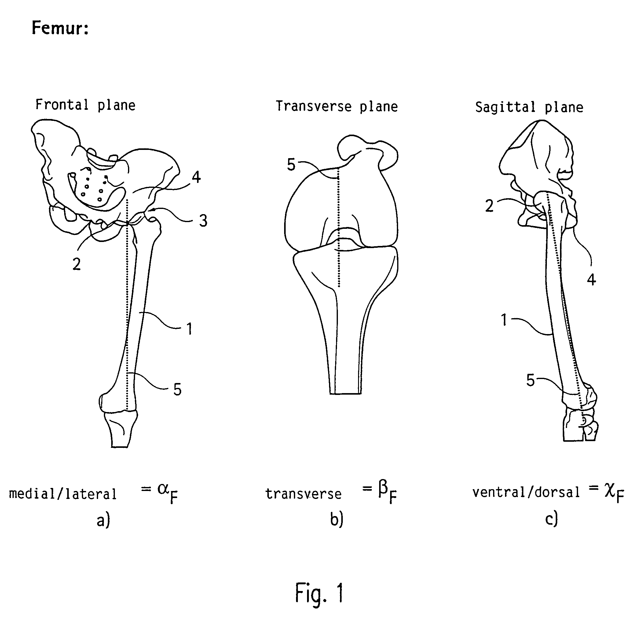
[0038]FIG. 1 shows how a mechanical axis of the leg of a healthy person is disposed with respect to the femur 1. The mechanical axis 5, drawn with a dashed line, in part (a) is seen from the front, so that its orientation in the medial / lateral direction αF is evident. The mechanical axis 5 is specified by a center of rotation 3 of a femoral head 2 in the socket of a hip joint 4, and by bony reference points in the region of the knee (distal end of the femur).

[0039]In the transverse plane, shown in part (b), the direction βF of the mechanical axis is defined by the piercing point or by the Whiteside line and the direction of the epicondylar axis or dorsal condylar axis.

[0040]In the sagittal plane, shown in part (c), the ventral / dorsal direction χF of the mechanical axis is fixed by the center of rotation 3 of the femoral head 2 and by bony reference points on the femur in the knee region, as in the frontal plane.

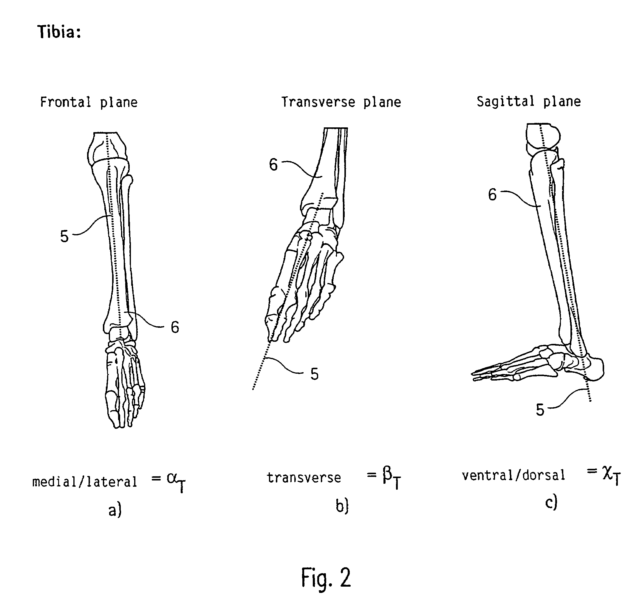
[0041]FIG. 2 shows, as another example of a mechanical axis of a limb in...


PUM


Abstract

A method of finding the position of a mechanical axis running in the longitudinal direction through a limb that is rotatably supported by its first end in a center of rotation that is not fixed and is not accessible for the mechanical determination of coordinates, by means of an optical coordinate-measurement device with an indicator to detect measurement-point coordinates in one rotational position of the limb such that, for each rotational position, a multi-point indicator rigidly attached near the second end of the limb signals several measurement-point coordinates, and, from the sets of measurement-point coordinates detected in a plurality of rotational positions, at least one group is selected that can be assigned to the same site of the center of rotation, and the measurement-point-coordinate sets assigned to this site of the center of rotation are used to calculate the mechanical axis.

Description

RELATED APLICATIONS[0001]This application is a continuation of U.S. application Ser. No. 10 / 363,488, filed Aug. 11, 2003, now U.S. Pat. No. 6,928,742. U.S. Ser. No. 10 / 363,488 is a national phase entry in the United States of the International Application PCT / EP01 / 05663 filed May 17, 2001 and claims the benefit of the German Patent Application No. DE100 42 965.3 filed Aug. 31, 2000.BACKGROUND OF THE INVENTION[0002]1. Field of the invention[0003]The invention relates to a method and an apparatus for finding the position of the mechanical axis of a vertebrate limb running in a longitudinal direction through a limb that is rotatably supported by its first end in a center of rotation that is not fixed and is not accessible for the mechanical determination of coordinates by means of a optical coordinate measurement device with an indicator to signal measurement point coordinates in one rotational position of the limb.[0004]2. Description Of The Related Art[0005]The mechanical axes of lim...

Claims


Application Information

Patent Timeline
Patent Type & Authority Patents(United States)
IPC IPC(8): A61B17/56A61B5/103G01B11/00A61B5/11A61B17/15A61B34/10A61B34/20A61B90/00
CPCA61B5/103A61B5/1079A61B5/4504A61B17/155A61B19/5244A61B5/6878A61B2019/508A61B2019/5255A61B2019/5268A61B2019/5272A61B2019/5483A61B2019/505A61B2090/3983A61B2034/2055A61B2034/2068A61B2034/2072A61B34/20A61B2034/105A61B2034/108
Inventor BROERS, HOLGERBERNER, WERNERHAURI, BERNHARDHAURI, THOMAS
Owner SMITH & NEPHEW ORTHOPAEDICS
Why Eureka
Try Eureka