[0018]A calibration of the measurement-point indicator, carried out before the actual measurement has begun, provides measurement-point coordinates that reproduce the distance and the angular positions of the above-mentioned
radiation sources with respect to one another on the multiple-point indicator. The measurement-point coordinates obtained from this calibration are compared, within a single coordinate
system, with the measurement-point coordinates detected in each rotational position. Subsequently those of the detected measurement-point coordinates that lie outside a prespecified tolerance range of the calibration measurement-point coordinates are eliminated; this measure is intended to exclude major errors in measurement that could be introduced, for example, by extraneous reflexes.
[0020]If the center of rotation had been precisely fixed during this procedure, all the measured points would lie on spherical surfaces around the center of rotation, and determination of its position would be fairly trivial. In practice, however, such fixation is not or at least not strictly achievable; instead, during the stepwise pivoting movement the center of rotation is repeatedly displaced. An element of the invention is to extract groups of measurement-point coordinate sets, each of which can be ascribed to a common center of rotation. Whereas for a fixed center of rotation it would not be strictly necessary to use multi-point indicators, the method in accordance with the invention does prefer such indicators to be employed. The sets of coordinates that they provide enable the evaluation involving averages in the error-minimizing calculation to be performed with a high degree of robustness and precision. From those sets of measurement-point coordinates that can be assigned to a group, in a
calculator device that forms part of the measurement apparatus several spherical surfaces are calculated, which represent the movement paths of the second end of the limb to which the indicator is attached. With the aid of these spherical surfaces the associated center points can be calculated simply and rapidly. The calculated center points correspond to the centers of rotation of the femur, or those relative to the active and / or passive
transmitter. This procedure makes it possible rapidly and easily to locate the center of femoral rotation in the pelvic
acetabulum, which is needed to specify the orientation of the mechanical axis, with no need for extra
surgery in the patient's
hip region.
[0023]As a result of such a geometrically correct and precise installation of the
knee prosthesis, the patient will experience improved mobility after the operation as well.
[0026]Important unknowns are a local translation vector, associated with translation of a
measurement point situated in the local coordinate
system (the origin of which is situated in the active or passive
transmitter), into the
global system, as well as a global translation vector and a
rotation matrix. The last two quantities serve to describe the translation of a
measurement point to the rotation point in the
global system, and the rotations of the local
system within the
global system. The application of an iterative calculation in determining the center of rotation makes possible a largely error-free determination of the center of rotation, even if the patient moves during the measurement.
[0027]An important boundary condition is the use of sterile measurement tools as well as an electronic / optical
measurement device in combination with the calculation device, which enables a more rapid completion of the measurement on the basis of optical data-transmission routes and
electronic data processing, which in turn reduces the time required for the operation.
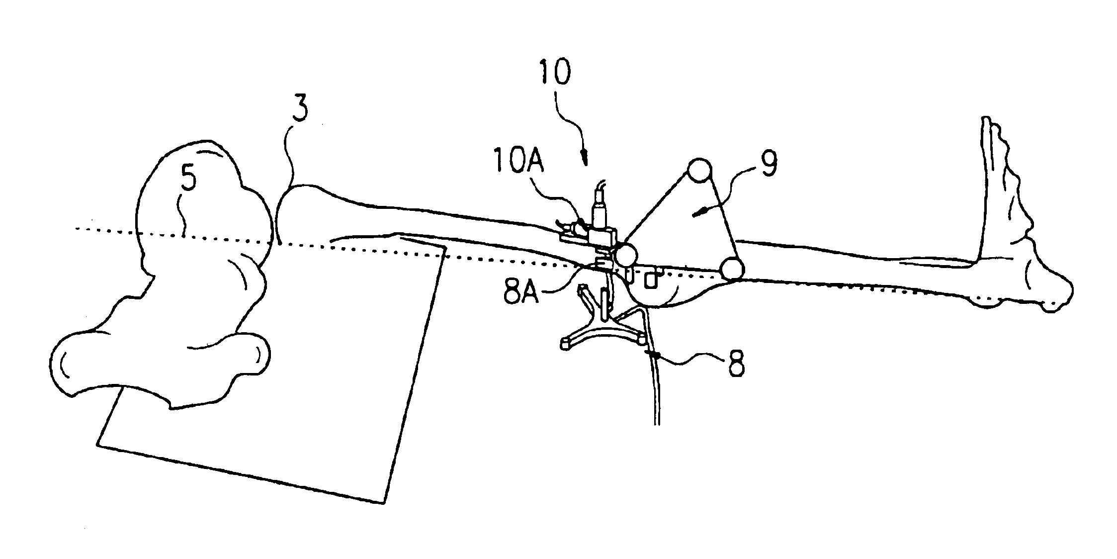
[0028]The mechanical axis is determined with the computer-assisted optical measurement device. It is defined by the center of rotation and the additional reference point at the distal end of the femur. Susequently, during the surgical procedure, the
cutting jig is positioned by means of the measurement device in such a way that the structures for mechanical guidance of the
cut are in the correct spatial orientation with respect to the patient's mechanical axis. This makes it possible for the
cut to be made so precisely that the deviation with respect to the mechanical axis is less than 1°.

