
Open-circuit testing system and method

a testing system and open-circuit technology, applied in the direction of electric connection testing, measurement devices, instruments, etc., can solve the problems of reducing the signal-to-noise ratio of the sensed signal, increasing the risk of erroneous determination of the connection state, and reducing the testability of the connection state between the integrated circuit and the printed circuit board. , to achieve the effect of advantageously reducing the error of determining the connection state due to insufficient capacitive coupling

Active Publication Date: 2009-11-03
TEST RES INC
View PDF10 Cites 3 Cited by
  • Summary
  • Abstract
  • Description
  • Claims
  • Application Information

AI Technical Summary

Benefits of technology

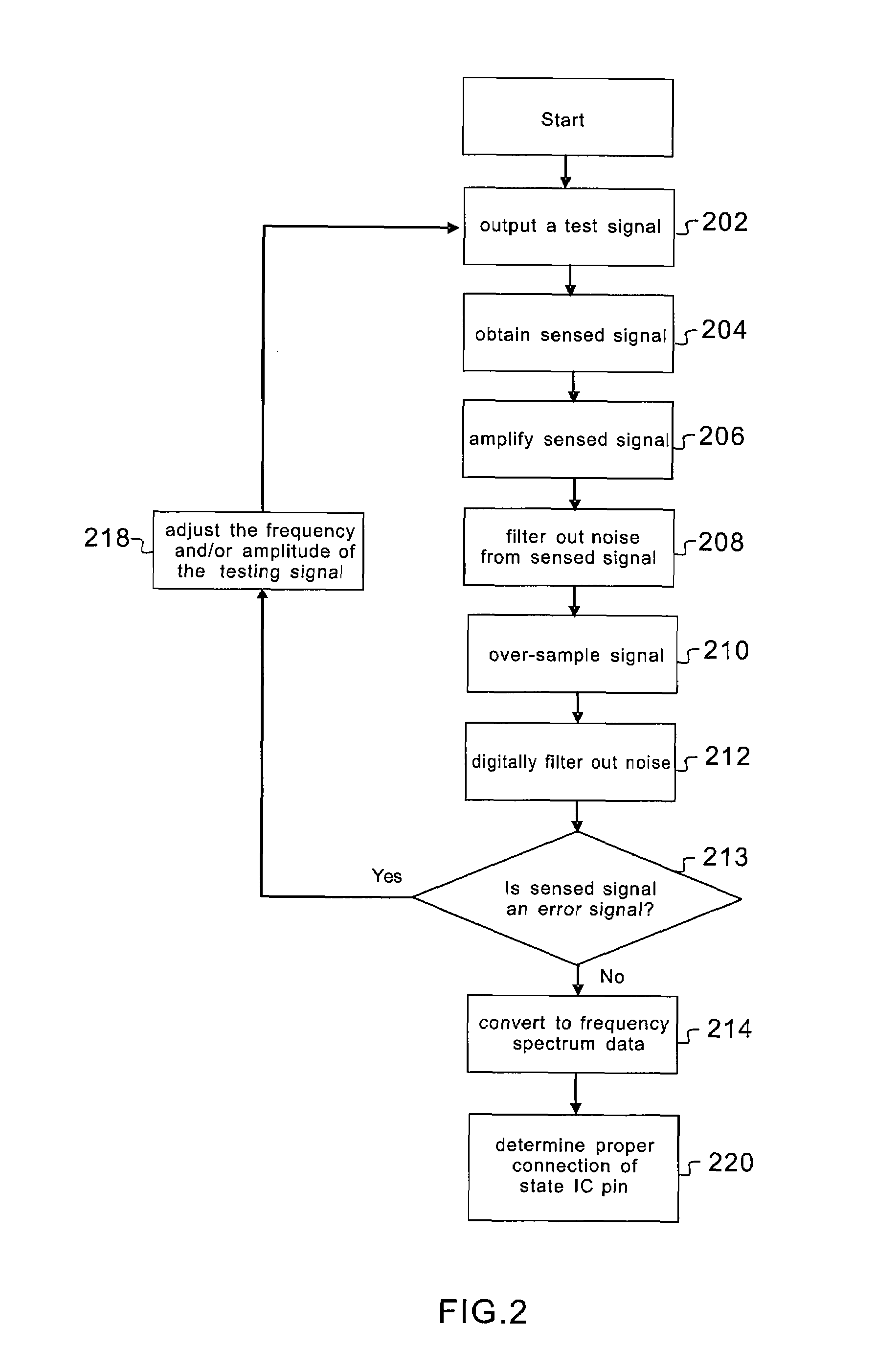
The patent describes a testing system and method for checking the connection state of a tested pin on an electronic component in an electronic device. The system uses a signal sensing unit to capture a signal from the tested pin, a signal processor to filter and over-sample the signal, and an analyzer to compute the signal and determine the connection state of the pin. The system also includes a validation test to confirm if the signal correctly reflects the connection state of the pin. The testing system reduces errors caused by insufficient capacitive coupling, which can occur when determining the connection state of a pin.

Problems solved by technology

Due to the shrinkage and modification in the geometry of the leads, an application of the above testing method will induce very weak capacitance coupling between the lead frame and the sensor plate, which reduces the signal-to-noise ratio of the sensed signal.
Consequently, the risk of erroneous determination of the connection state is increased, and the testability of the connection state between the integrated circuit and the printed circuit board drops.
Unfortunately, about 30% to 40% of the tested pins of a standard ball grid array package induce a capacitive coupling below the threshold value, which results in a reduced coverage of the testing method using capacitive coupling.
Thus, the conventional testing method is not adapted for ball grid array package manufacturing lines, especially for testing packaged integrated circuits with high-density pins that induce very weak capacitive coupling.
However, the disclosed approaches equally fail to effectively address the issue of weakened capacitive coupling due to a higher density of the tested pins.

Method used


Image

  • Open-circuit testing system and method
  • Open-circuit testing system and method
  • Open-circuit testing system and method

Examples


Embodiment Construction

[0017]The application describes a testing system and method for determining the connection state of a tested pin of an electronic component mounted in an electronic device assembly. The electronic component may include, but is not limited to, an integrated circuit, a connector or similar components provided in an electronic device assembly such as a printed circuit board assembly.

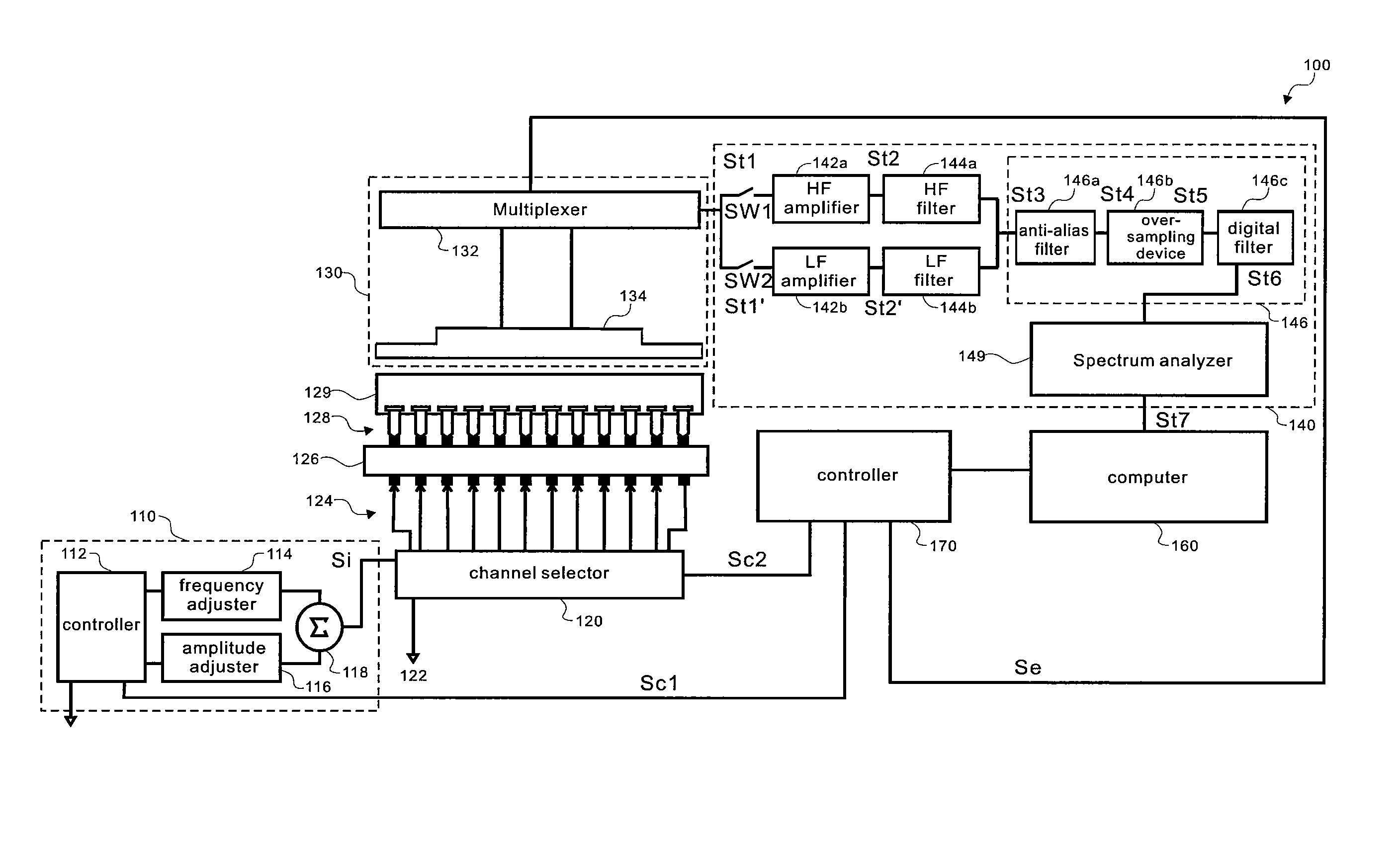
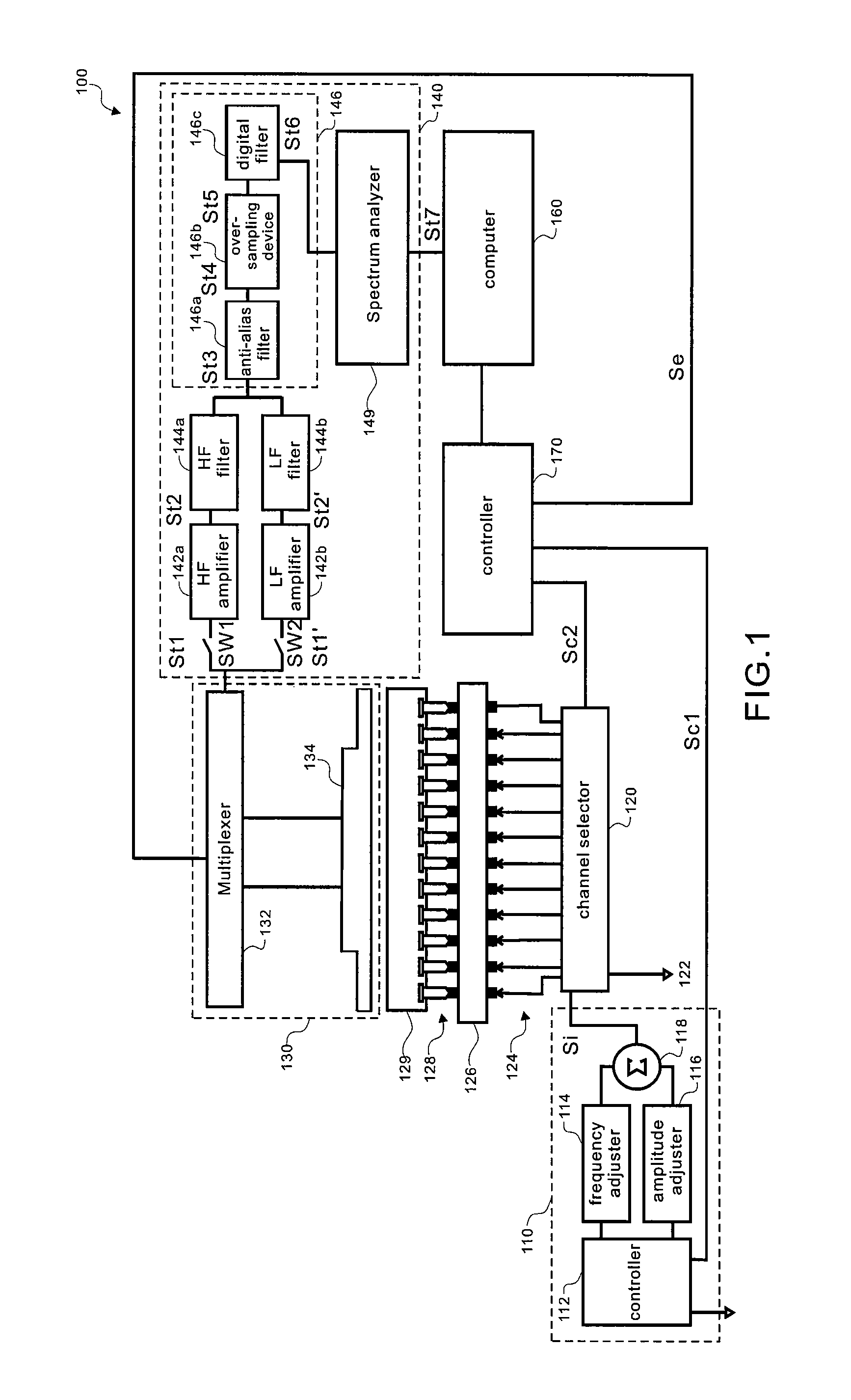
[0018]FIG. 1 is a block diagram of a testing system according to an embodiment of the invention. Reference number 100 designates a testing system suitable for determining the connection state of an electronic device assembly, for example, comprised of a printed circuit board 126 and an integrated circuit 129. The testing system 100 includes a testing signal source 110, channel selector 120, signal sensing unit 130, signal processor unit 140, computer 160 and controller 170.

[0019]The testing signal source 110 comprises a signal source controller 112, programmable frequency adjuster 114, programmable amplitud...


PUM


Abstract

The invention discloses a testing system and method suitable for determining the connection state of an electronic component in an electronic device assembly. In an embodiment, the testing system comprises a signal sensing unit configured to provide a sensed signal induced by capacitive coupling in response to the output of a testing signal passing through a tested pin, a signal processor unit configured to filter and over-sample the sensed signal to obtain a digital signal, and an analyzer unit configured to compute the digital signal for determining a connection state of the test pin.

Description

CROSS-REFERENCE TO RELATED APPLICATIONS[0001]This application claims priority of Taiwan application No. 096108085, filed on Mar. 8, 2007.FIELD OF THE INVENTION[0002]The invention relates to a testing system and method for determining the connection state of an electronic component in an electronic device assembly. More particularly, the invention discloses a testing system and method that use capacitive coupling for determining the connection state of a tested pin of an electronic component in an electronic device assembly.DESCRIPTION OF THE RELATED ART[0003]In the manufacture of a printed circuit board assembly, an essential testing stage consists of determining whether every integrated circuit (IC) or connector is properly connected to the print circuit board. This testing, also commonly called “open-circuit” testing, detects manufacture defects so that the occurrence of test failures in a subsequent functional testing can be reduced. Conventionally, an in-circuit tester uses a ma...

Claims


Application Information

Patent Timeline
Patent Type & Authority Patents(United States)
IPC IPC(8): G01R31/00G01R31/02
CPCG01R31/046G01R31/304G01R31/312G01R31/70
Inventor CHEN, CHIEN-WEICHEN, CHIA-MING
Owner TEST RES INC
Learn More