Apparatus and method for accurately converting groove/land polarity upon groove/land track change on optical medium

a technology of optical medium and polarity, applied in the field of accurately converting groove/land polarity, can solve the problems of insufficient accuracy, inability to accurately determine, and often unstable detection of envelope signals, etc., and achieve the effect of accurately converting a groove/land polarity

Inactive Publication Date: 2009-11-03
MEDIATEK INC
View PDF13 Cites 0 Cited by
  • Summary
  • Abstract
  • Description
  • Claims
  • Application Information

AI Technical Summary

Benefits of technology

[0002]The present invention relates to an apparatus and method for accurately converting groove / land polarity, and especially in an apparatus and method capable of toggling a reliable and exact groove / land polarity upon determination of a groove / land track change on an optical medium.
[0007]To address the foregoing drawbacks, it is, therefore, a primary objective of the present invention to provide an apparatus and method for accurately converting a groove / land polarity upon determination of a groove / land track change on an optical medium, which merely needs to initially find out a reference groove / land changing point on the optical medium, or pick up any one decoded physical identification data (PID) on the optical medium, and then is cable of timely and accurately determining the next groove / land changing points for converting groove / land polarity, even all of the next track changing points distributed on the optical medium, especially for one kind of optical medium which has to use an exact groove / land information to perform a stable servo control. Also, the present invention need not to decode the last sectors for finding out each one of the groove / land changing points on the optical medium.
[0008]To achieve the aforementioned objectives, a first embodiment of the present invention introduces an apparatus for accurately determining a groove / land polarity upon a groove / land track change on an optical medium, which includes a reference groove / land detector, a sector information unit, a sector counter, a comparator and a groove / land toggling unit. Meanwhile, the reference groove / land detector is operative to initially detect a reference groove / land changing point in a zone of the optical medium. The sector information unit as a lookup table pre-stores some sector information relative to the optical medium, thereby providing a first value indicating a total number of sectors per track based on to the detected zone on the optical medium. The sector counter is operative to count up a number of sectors per a predetermined cycle, from the reference groove / land changing point to approach a subsequent groove / land changing point along the track where the reference groove / land changing point belongs, and the number of sectors counted per cycle is set to be a second value. The comparator compares the first value with the second value to determine the subsequent groove / land changing point occurs on the optical medium or not. While the first value is found identical with the second value, the groove / land polarity conversion is performed at a header.

Problems solved by technology

However, the envelope signal is often unstable to be detected during slice and therefore is insufficient to accurately determine the groove / land polarity toggle point.
However, as long as the physical identification data of the last 3 sectors in each track all fails to be decoded, the mechanism also fails to determine an exact groove / land changing position.

Method used


Image

  • Apparatus and method for accurately converting groove/land polarity upon groove/land track change on optical medium
  • Apparatus and method for accurately converting groove/land polarity upon groove/land track change on optical medium
  • Apparatus and method for accurately converting groove/land polarity upon groove/land track change on optical medium

Examples


Embodiment Construction

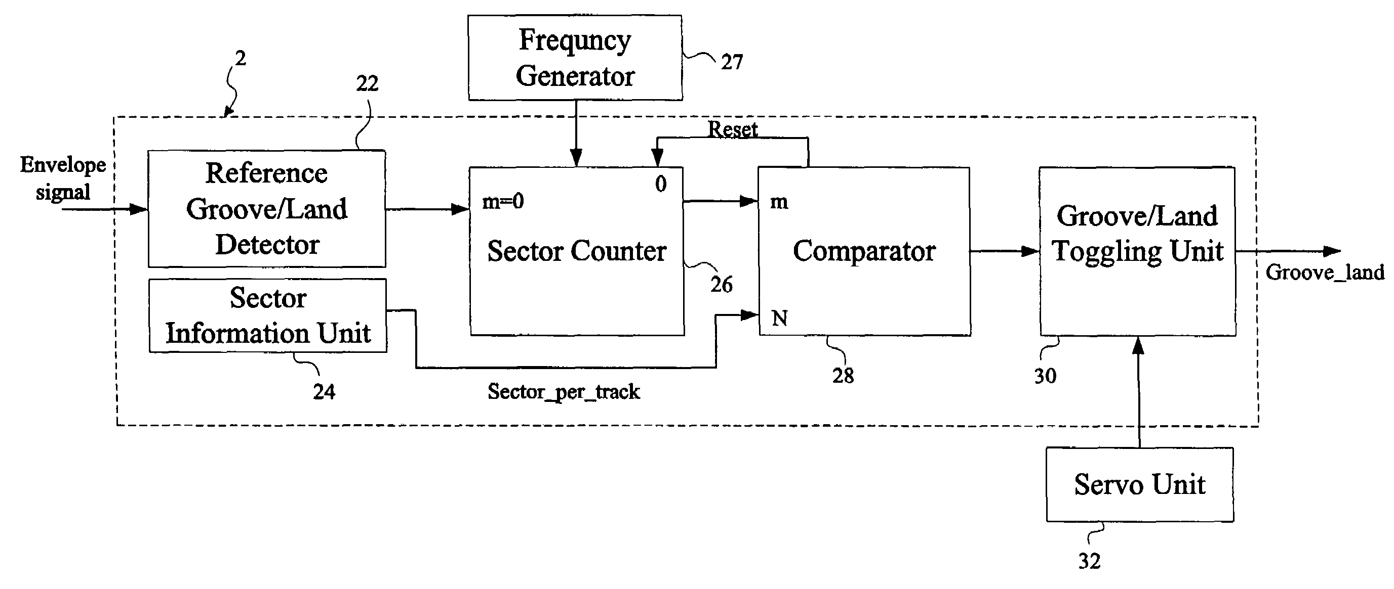
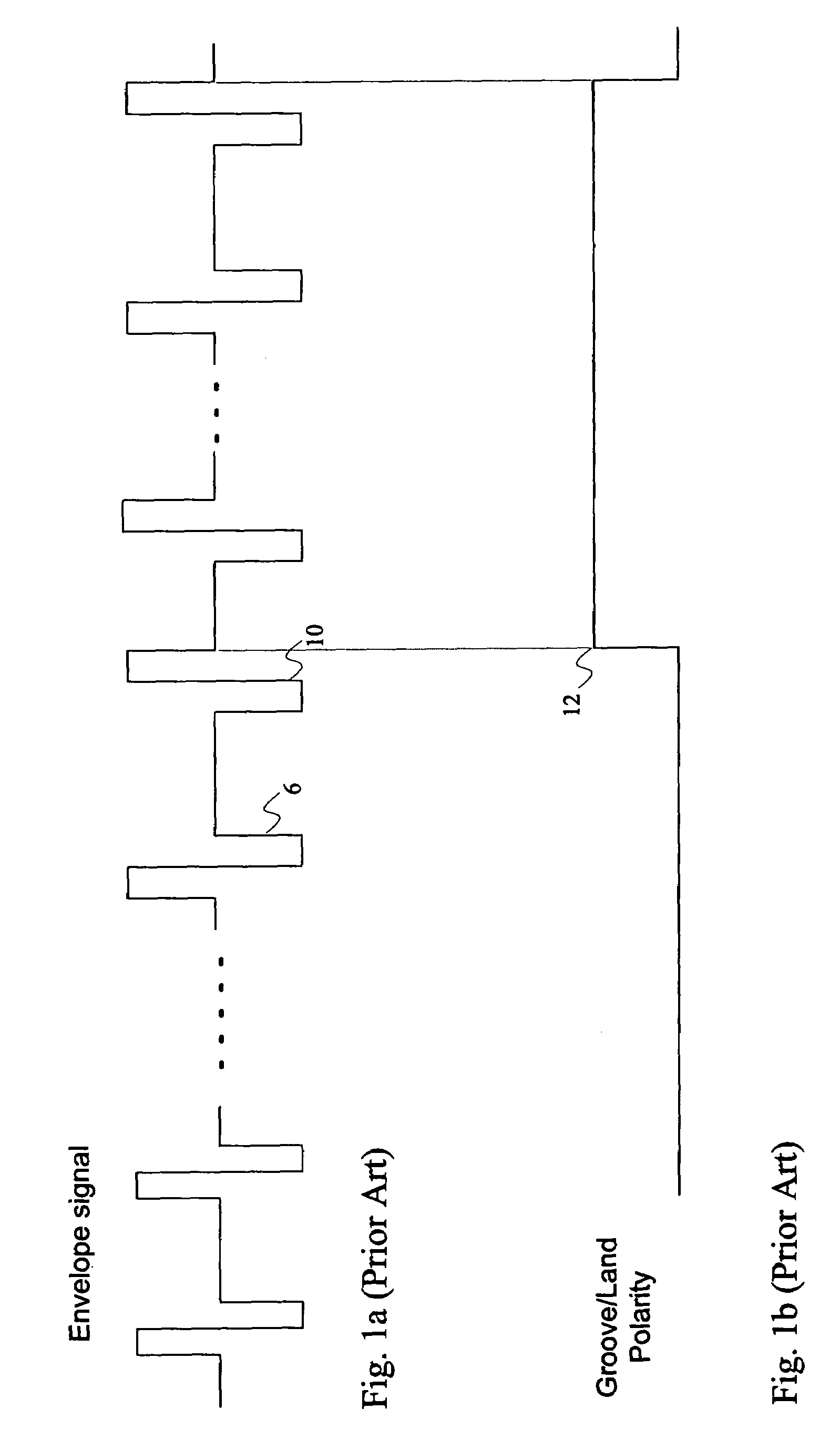
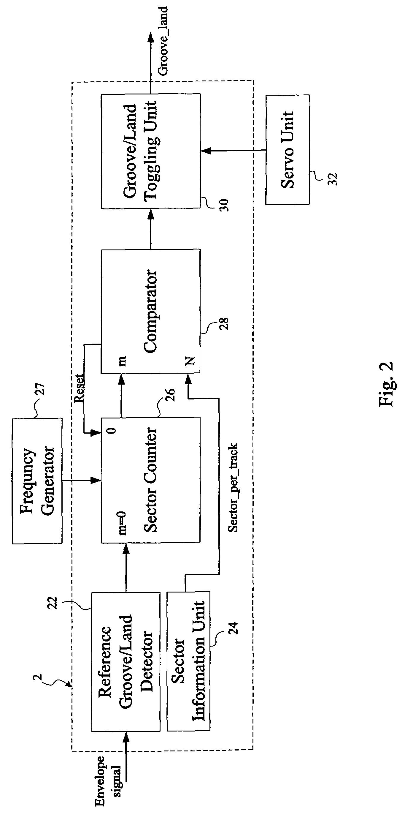
[0046]Referring to FIG. 2, a track-polarity converting apparatus 2 according to a first embodiment of the present invention for accurately converting a groove / land polarity responsive to a groove / land track change on an optical medium (not shown), comprises a reference groove / land detector 22, a sector information unit 24, a sector counter 26, a comparator 28 and a groove / land toggling unit 30. The reference groove / land detector 22 is operative to seek initially a reference groove / land changing point formed on the optical medium, depending upon a polarity change of an envelope signal as illustrated in FIG. 1a. In another case, a groove / land changing point also can be found by way of counting cycles of the wobble signal to acknowledge the number of sectors per track. As long as the reference groove / land changing point is found, the reference groove / land detector 22 will set a number value (i.e. “m”) of sector as zero for beginning of the sector number counting (i.e. “m=m+1”, detailed...


PUM

PropertyMeasurementUnit
polarityaaaaaaaaaa
phase differenceaaaaaaaaaa
physical identificationaaaaaaaaaa

Abstract

The present invention discloses an apparatus and method for accurately converting a groove / land polarity upon a groove / land track change on an optical medium, by way of initially deciding a reference groove / land changing point or a decoded PID of any one specific sector formed on the optical medium. By counting a specific number of sectors from the reference groove / land changing point or the specific sector, a subsequent groove / land changing point will easily be approached for converting the groove / land polarity, and even the other oncoming track changing points on the optical medium also can be determined.

Description

CROSS-REFERENCE TO RELATED APPLICATION[0001]The present application claims the benefit of the filing date under 35 U.S.C. § 119(e) of a Provisional U.S. Patent Application No. 60 / 730,183, filed Oct. 25, 2005, which is incorporated by reference herein.[0002]The present invention relates to an apparatus and method for accurately converting groove / land polarity, and especially in an apparatus and method capable of toggling a reliable and exact groove / land polarity upon determination of a groove / land track change on an optical medium.[0003]Recently, various types of disk-shaped optical medium with high-density capacity was progressively developed in compliance with trends of accommodating huge amounts of digital contents, for instance, video or audio data. For one kind of disk-shaped optical medium such as DVD+RW, the data is recorded by a pickup head of a recording / reading device in grooves as pits formed on the surface of the optical medium. For another kind of disk-shaped optical med...

Claims


Application Information

Patent Timeline
Patent Type & Authority Patents(United States)
IPC IPC(8): G11B27/36G11B20/10
CPCG11B7/0901G11B7/00718
Inventor LIN, MENG-HSUEH
Owner MEDIATEK INC
Why Eureka
Try Eureka