Mammography apparatus

a technology of mammography and apparatus, which is applied in the field of mammography apparatus, can solve the problems of inability to invariably place the breast on the center of the object table, the subject is burdened, and the density of the image is inappropriate,

Active Publication Date: 2009-11-03
FUJIFILM CORP
View PDF16 Cites 26 Cited by
  • Summary
  • Abstract
  • Description
  • Claims
  • Application Information

AI Technical Summary

Benefits of technology

[0063]According to the present invention, the detecting position of the dose detector is moved according to the size of the breast to be imaged such that the detecting position corresponds to the central portion of the breast. Thus, an image having an appropriate density may be obtained with minimum exposure of radiation to the subject.
[0065]Still further, by detecting the size of the breast from the image information, the center of the breast may be detected accurately, and thereby the dose of radiation may be detected at a more appropriate position.

Problems solved by technology

If the pressing pressure is too low, however, the mammary glands, fat, blood vessels and the like overlap with each other.
Therefore, when the two-directional imaging is performed for the right and left breasts of a subject, such adjustments are required to be made four times, causing a considerable burden on the subject.
The burden on the subject may be alleviated by storing information related to the pressing pressure and the like as proposed in the aforementioned patent publication, but it is difficult to invariably place the breast on the center of the object table.
Consequently, there may be a case that the density of the image is inappropriate.
But, the object table having a flat panel detector accommodated therein is expensive, so that it may be difficult to invariably provide both the large and small platforms.
This may result in the image having an inappropriate density.
Further, use of a large platform for imaging a small breast causes a problem that it is hard for the operator to withdraw its hand after positioning the breast.

Method used


Image

  • Mammography apparatus
  • Mammography apparatus
  • Mammography apparatus

Examples


Embodiment Construction

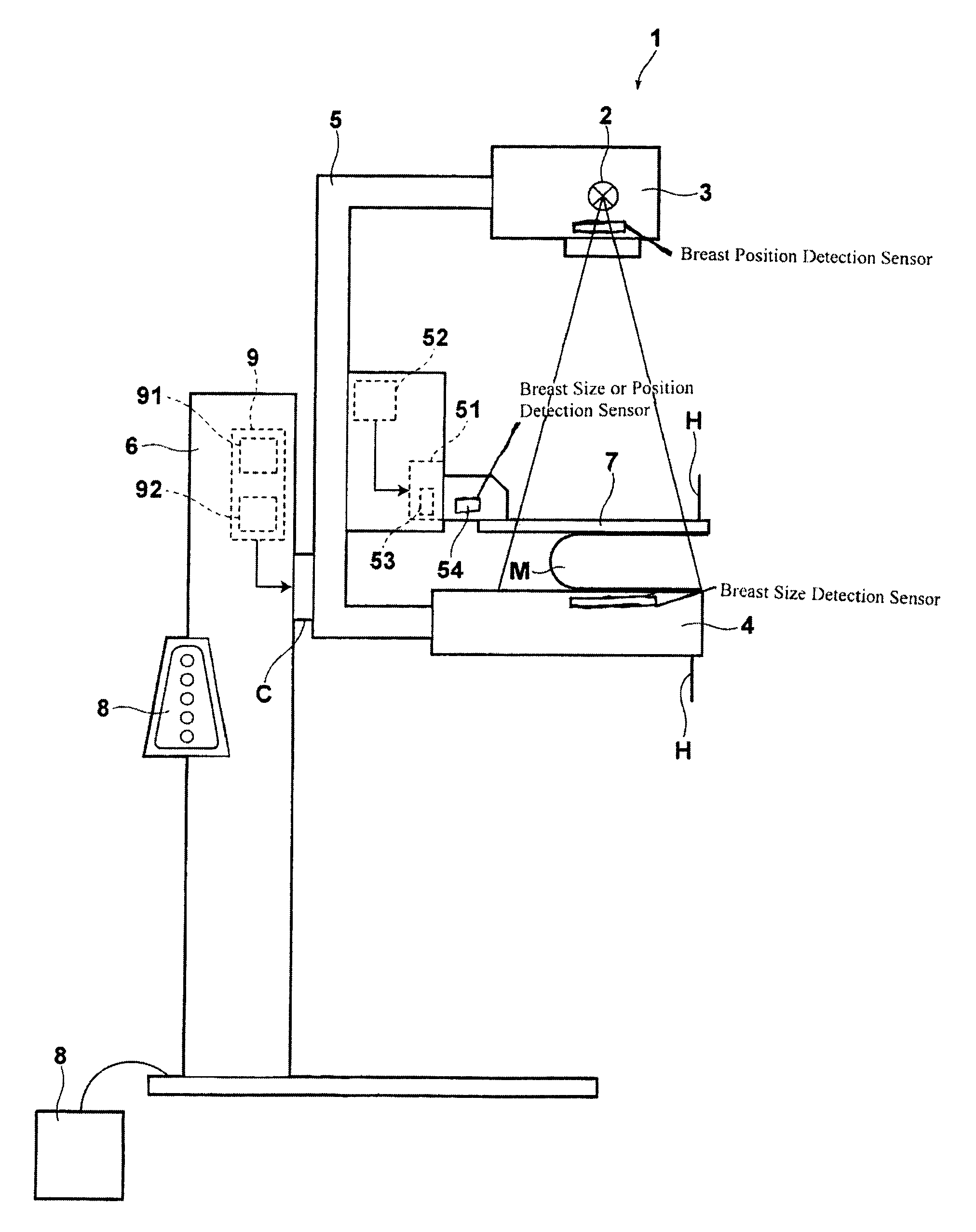
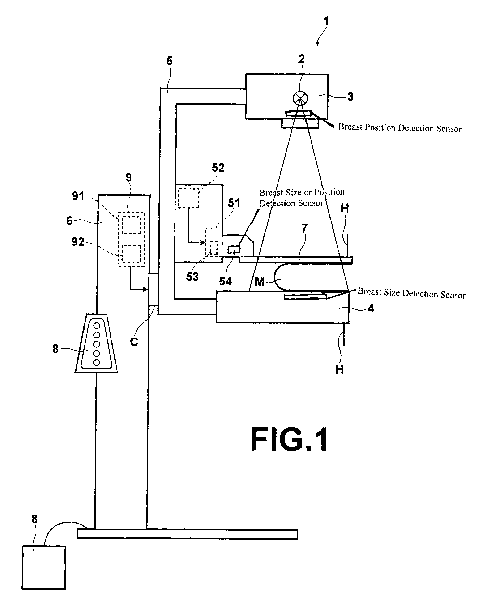
[0092]Hereinafter, exemplary embodiments of the present invention will be described with reference to the accompanying drawings. FIG. 1 is a schematic view of the mammography apparatus according to a first embodiment of the present invention, and FIG. 2 is a front view of the arm section of the mammography apparatus.

[0093]The mammography apparatus 1 includes: a radiation irradiation section 3 having therein a radiation source 2; an object table 4 having therein a recording medium holding section, such as a cassette or the like, in which a recording medium, such as a flat panel detector 10 or the like is accommodated; an arm 5 connecting the radiation irradiation section 3 and object table 4 such that they face each other. The arm 5 is attached to a base 6 through a spindle C.

[0094]The base 6 further includes: an operation section 8 for use by the operator to control the height of the platform 4 (i.e., height of the arm 5), and inclination of the platform 4 (i.e., inclination of the ...


PUM


Abstract

A mammography apparatus capable of obtaining a breast image having an optimum density with reduced burden on the subject. The apparatus includes a radiation irradiation section and an object table connected to an arm such that they face each other, and the breast compressed onto the object table using a compression paddle is imaged by rotating the arm by an arm rotation means according to the imaging direction. In the apparatus, the size of the breast is detected, and the position of a dose detector is moved along the side of the object table facing the chestwall of the subject according to the detected size of the breast and the angle of rotation of the arm when rotated by the arm rotation means.

Description

BACKGROUND OF THE INVENTION[0001]1. Field of the Invention[0002]The present invention relates to a mammography apparatus for obtaining a breast image.[0003]2. Description of the Related Art[0004]Breast cancer screenings are conducted using X-ray machines dedicated to breast imaging (mammography apparatus), since the discovery rate of early stage cancer is increased by combining mammograms obtained by the mammography apparatus with clinical breast examinations rather than depending only on the clinical breast examinations.[0005]General breast cancer screenings include a unidirectional imaging (two images) and a two-directional imaging (four images). In the unidirectional imaging, only the MLO (mediolateral oblique) imaging is conducted. In the MLO imaging, the breast is clamped and imaged from the oblique direction so that the greater pectoral muscles are imaged as shown in FIG. 14A. In order to enable the imaging from such direction, the mammography apparatus includes an arm to whic...

Claims


Application Information

Patent Timeline
Patent Type & Authority Patents(United States)
IPC IPC(8): A61B6/04
CPCA61B6/0414A61B6/502A61B6/4494A61B6/544A61B6/542
Inventor SENDAI, TOMONARI
Owner FUJIFILM CORP
Why Eureka
Try Eureka