
Method, apparatus and program for selective registration three-dimensional tooth image data to optical scanning tooth model

a three-dimensional, tooth image technology, applied in the field of tooth image registration, can solve the problems of inaccurate tooth shape, noise in the data loss of parts, and the accuracy of tooth parts themselves, so as to improve the accuracy of tooth image registration. , the effect of accurate tooth shap

Active Publication Date: 2018-05-03
KOREA INST OF SCI & TECH
View PDF10 Cites 16 Cited by
  • Summary
  • Abstract
  • Description
  • Claims
  • Application Information

AI Technical Summary

Benefits of technology

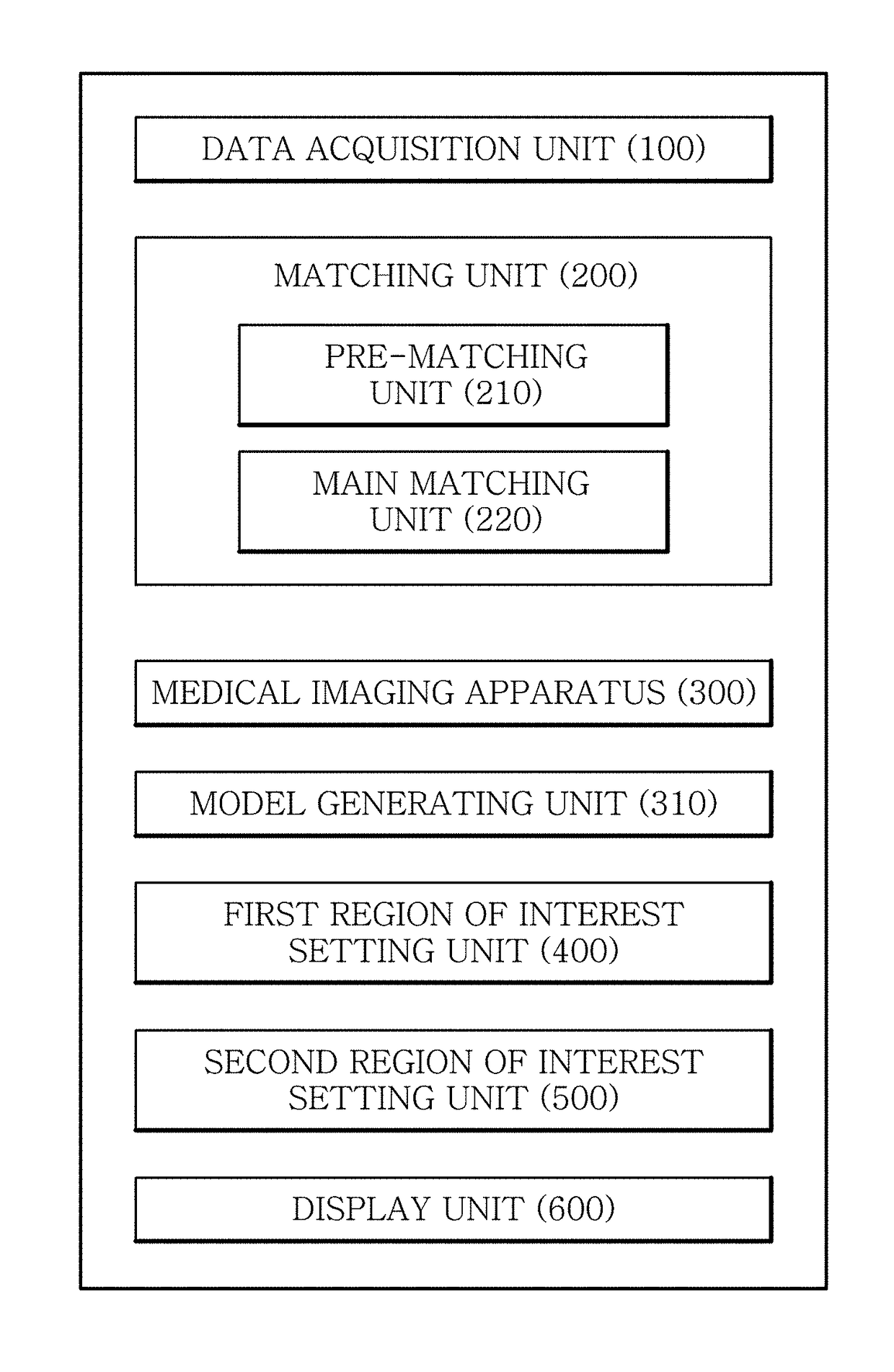
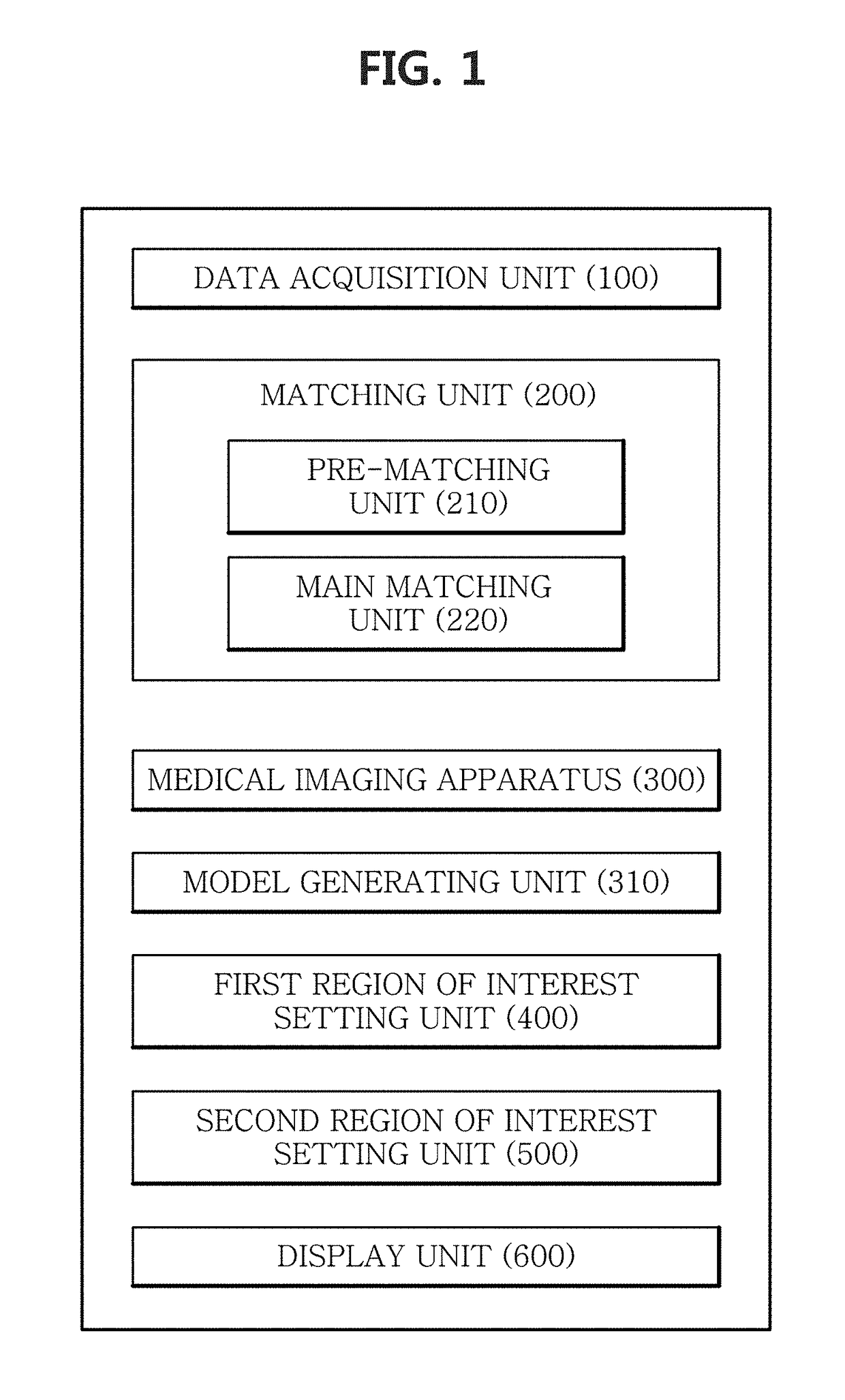
The present patent provides a method and apparatus for registering a tooth structure to a patient's minimum exposure to CBCT and reduced amount of radiation exposure through optical scanning. This method improves the accuracy of the tooth image and allows for a model with an accurate tooth shape to be easily obtained. This model can be used in virtual surgical planning, calibration, and implant procedures. Overall, this technology provides a more accurate and efficient means for tooth image registration.

Problems solved by technology

However, images of teeth (surface, structure, etc.) themselves are not obtained accurately, and when there is a metal material such as a calibration device and dental prosthesis on or around teeth, CT images may contain noise such as ghosting or artifact, resulting in data loss at a part containing noise.
Its consequential problem is that the teeth shape is inaccurate and distorted teeth images are obtained.
The foregoing earlier technologies require patients' exposure to CBCT scans multiple times, increasing the patients' amount of radiation exposure, and fail to scan accurate teeth structures and have limitations in obtaining accurate teeth images.

Method used


Image

  • Method, apparatus and program for selective registration three-dimensional tooth image data to optical scanning tooth model
  • Method, apparatus and program for selective registration three-dimensional tooth image data to optical scanning tooth model
  • Method, apparatus and program for selective registration three-dimensional tooth image data to optical scanning tooth model

Examples


Embodiment Construction

[0043]Embodiments will be described with reference to the accompanying drawings. However, the disclosed principles may be implemented in many different forms and should not be understood as being limited to the disclosed embodiments. In the detailed description, certain detailed description of well-known features and technology may be omitted herein to avoid rendering the features of the embodiments unnecessarily vague.

[0044]In the drawings, reference numerals in the drawings indicate components. For clarity, the shape, size, area, etc. in the drawings may be exaggerated.

[0045]The term “image” as used herein refers to multi-dimensional data composed of discrete image elements (for example, pixels in a 2-dimensional (2D) image and voxels in a 3-dimensional (3D) image). For example, the image may include medical images of an object obtained by X-ray, CT, MRI, an ultrasonic wave, and other medical imaging system.

[0046]The “object” may include a human or an animal or parts of a human or...


PUM


Abstract

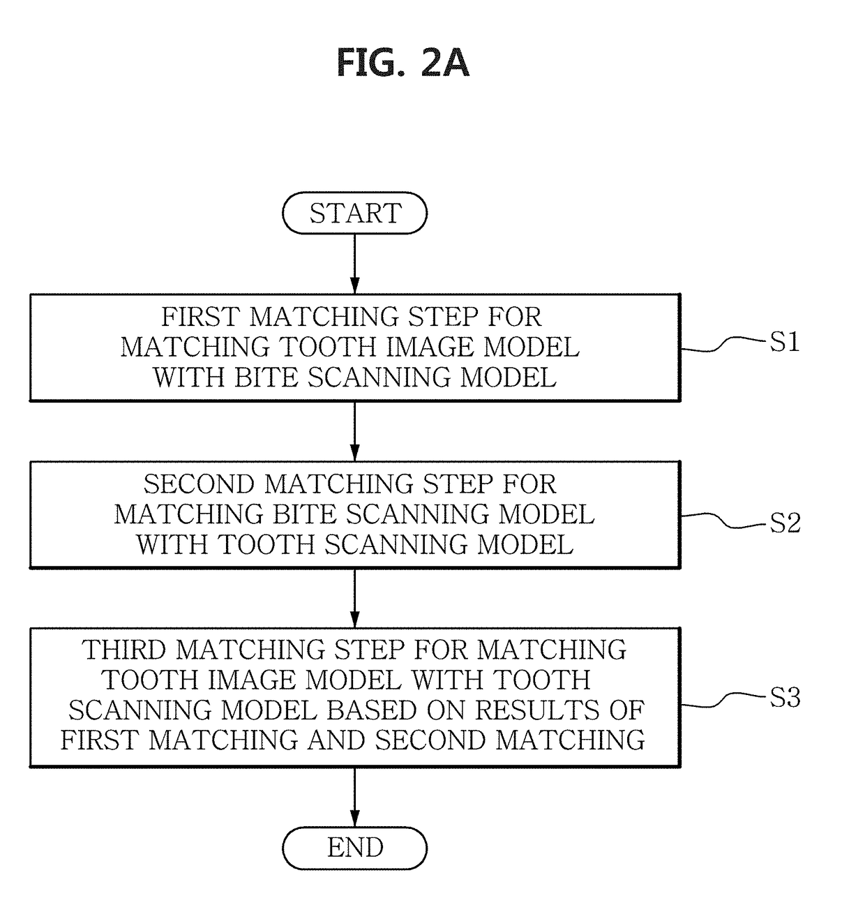
A method for registering a tooth image with a tooth structure according to an embodiment includes a first registering step for registering a tooth image model obtained from a medical image taken when an object bites a bite including a marker with a bite scanning model obtained by scanning the bite, a second registering step for registering the bite scanning model with a tooth scanning model obtained by scanning a tooth shape of the object, and a third registering step for registering the tooth image model with the tooth scanning model based on the results of the first registering step and the results of the second registering step. As a result, a model including an accurate shape of tooth part difficult to obtain from a medical imaging apparatus can be easily obtained.

Description

TECHNICAL FIELD[0001]The present disclosure relates to a method for registering a tooth image model obtained from a three-dimensional tooth imaging apparatus with an accurate tooth image, and more particularly, to an image model registering method for performing registration of a tooth image model, a bite model obtained by an optical scanner and a tooth scanning model, and an apparatus and a computer program therefore.DESCRIPTION OF THE RELATED ART[0002]In surgeries near teeth such as implant, double jaw surgery and calibration, it is necessary to obtain accurate medical images for detailed surgical planning. To obtain patients' medical images, Computed Tomography (CT) has been used, and recently, many dental facilities primarily use Cone-Beam Computed Tomography (CBCT) to diagnose patients' teeth and obtain teeth images. General methods for obtaining teeth images using CT and CBCT are relatively easy to extract skin and facial bones. However, images of teeth (surface, structure, et...

Claims


Application Information

Patent Timeline
IPC IPC(8): G06T7/33A61B6/14A61B5/055A61B6/03A61B6/00A61C19/05A61C9/00
CPCG06T7/344A61B6/14A61B5/055A61B6/032A61B6/4085A61C19/05A61C9/0046G06T2207/30204G06T2207/30036G06T2210/41G06T2207/20104A61C9/0053A61B5/4542G06T2207/10028G06T2207/10081A61B6/51A61B5/0088A61B5/742G06T11/008G06T2207/20221
Inventor KIM, YOUNGJUNCHOLEE, DEUKHEEKIM, LAEHYUNPARK, SE HYUNGLEE, JUNG-WOO
Owner KOREA INST OF SCI & TECH
Learn More