Multiplexer and wireless receiver
a wireless receiver and multi-channel technology, applied in the field of wireless communication multi-channel receivers and wireless communication, can solve the problems of signal distortion, signal noise increase, and each signal generates intermodulation distortion
- Summary
- Abstract
- Description
- Claims
- Application Information
AI Technical Summary
Problems solved by technology
Method used
Image

Examples
first embodiment
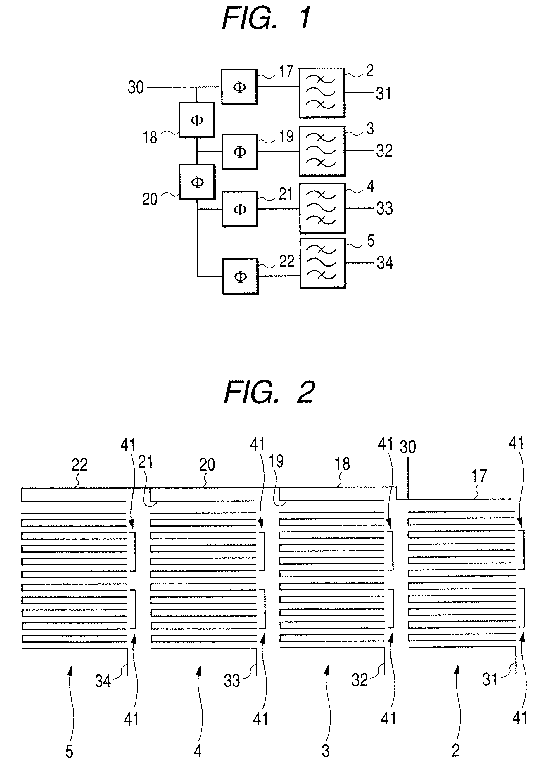
[0022]FIG. 1 is an exemplary circuit diagram of the multiplexer according to the first embodiment.
[0023]As shown in FIG. 1, a signal inputted from an input portion 30 passes band-pass filters 2, 3, 4 and 5 for the corresponding channels through delay circuits 17, 18, 19, 20, 21 and 22 and is outputted from the output portions 31, 32, 33 and 34 for the respective channels. Particularly, the delay circuit 17 is directly connected to the input portion. The band-pass filter 2 is directly connected to the delay circuit 17.
[0024]Now it is assumed that each of the delay circuits 17 to 22 includes a line with an impedance of 50Ω and with an optimum electrical length for providing a desired branching characteristic. The circuit parameter of each of the band-pass filters 2 to 5 for the corresponding channels may be optimized to provide their desired branching characteristic.
[0025]FIG. 2 is a schematic view of the layout for realizing the multiplexer circuit shown in FIG. 1.
[0026]A superconduc...
first example
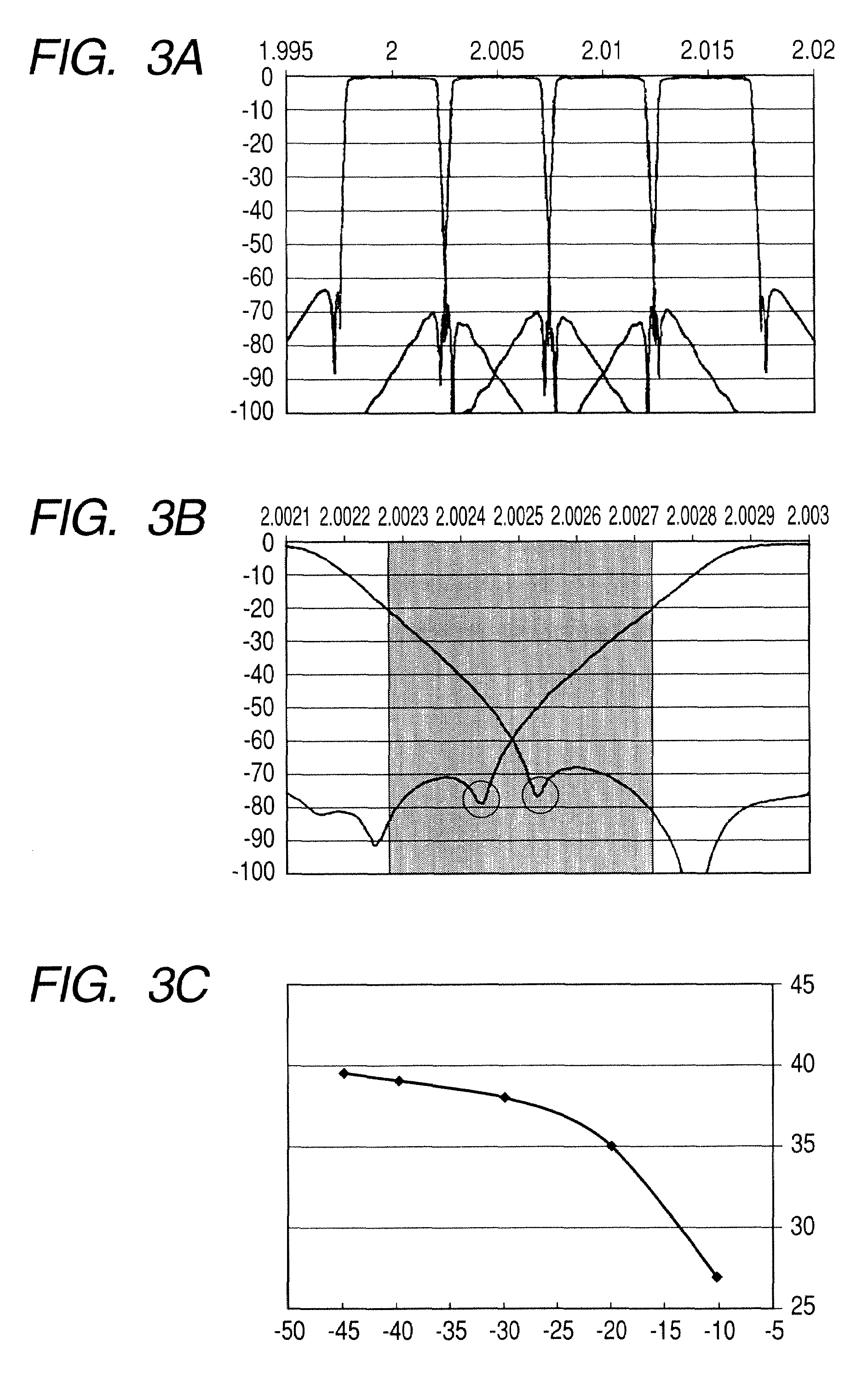
[0035]Assuming that f1=2.000 GHz and f2=2.005 GHz,
f1
is satisfied.
[0036]The branching characteristic of the band-pass filter for the first-channel has an attenuation pole at fa1=2.00253 GHz and the branching characteristic of the band-pass filter for the second-channel has an attenuation pole at fa2=2.00243 GHz. Then,
f1
fa2
f2−fa1f2−f1) / 2 (4)
fa2−f1f2−f1) / 2 (5)
are satisfied.
[0037]The branching characteristic of the band-pass filter for the second channel at fa1 is −49.97 dB not larger than −20 dB. Further, the branching characteristic of the band-pass filter for the first channel at fa2 is −46.00 dB not larger than −20 dB.
[0038]By satisfying the relationships (1) to (5), the attenuation poles can be located within the guard band for the first and second channels. Thus, the transient signal degradation can be suppressed thereby to realize the desired branching characteristic for the adjacent channel. Incidentally, the guard band is determined according to the c...
second example
[0039]Assuming that f1=2.005 GHz and f2=2.010 GHz, relationship (1) is satisfied.
[0040]The branching characteristic of the band-pass filter for the first-channel has an attenuation pole at fa1=2.00758 GHz and the branching characteristic of the band-pass filter for the second-channel has an attenuation pole has an attenuation pole at fa2=2.00742 GHz. Then, the relationships (2) to (5) are satisfied.
[0041]The branching characteristic of the band-pass filter for the second channel at fa1 is −39.68 dB not larger than −20 dB. Further, the branching characteristic of the band-pass filter for the first channel at fa2 is −40.32 dB not larger than −20 dB. Namely, by satisfying the above relationships, the attenuation poles can be located within the guard band for the first and second channels. Thus, the transient signal degradation can be suppressed thereby to realize the desired branching characteristic for the adjacent channel.
PUM
 Abstract
Description
Claims
Application Information
 - R&D Engineer
- R&D Manager
- IP Professional
- Industry Leading Data Capabilities
- Powerful AI technology
- Patent DNA Extraction
Browse by: Latest US Patents, China's latest patents, Technical Efficacy Thesaurus, Application Domain, Technology Topic.
© 2024 PatSnap. All rights reserved.Legal|Privacy policy|Modern Slavery Act Transparency Statement|Sitemap