Straight traveling hydraulic circuit

a hydraulic circuit and straight travel technology, applied in the direction of steering parts, non-deflectable wheel steering, couplings, etc., can solve the problems of left or right declination of equipment, failure to keep the traveling pressure of heavy construction equipment straight, and equipment declination, so as to improve the traveling operation and prevent equipment declination or sudden traveling

Inactive Publication Date: 2009-11-10
VOLVO CONSTR EQUIP HLDG (SWEDEN) AB
View PDF9 Cites 17 Cited by
  • Summary
  • Abstract
  • Description
  • Claims
  • Application Information

AI Technical Summary

Benefits of technology

[0027]One object of the present invention is to provide a straight traveling hydraulic circuit, which, in case of performing a combined operation in which a fine operation of a working device and a fine traveling of a traveling device are simultaneously required, can allow heavy construction equipment to operate independent of the working device, thereby preventing a declination or sudden traveling of the equipment, improving the traveling operation, and increasing the working efficiency.

Problems solved by technology

As a result, the left and right traveling pressure is not balanced.
This results in a failure in keeping the heavy construction equipment travel straight and thereby creating a left or right declination of the equipment.
Also, a shock such as a sudden traveling happens due to the sudden supply of the hydraulic fluid to the traveling device.
This results in reduction of the operability of the traveling device and the working efficiency.
As a result, the straight traveling is not ensured dependent of the working device, and the traveling device is supplied with the pressure according to the shift of the control valve for the working device.
Therefore, the left and right traveling pressure is not balanced, thereby creating left or right declination or sudden traveling of the equipment and thus reducing the operability of the traveling device.
In addition, if the traveling side pressure is high and the working device side pressure is low, the hydraulic fluid travels to the working device, thereby decreasing the working efficiency.

Method used


Image

  • Straight traveling hydraulic circuit
  • Straight traveling hydraulic circuit
  • Straight traveling hydraulic circuit

Examples


Embodiment Construction

[0039]Hereinafter, preferred embodiments of the present invention will be described with reference to the accompanying drawings. The matters defined in the description, such as the detailed construction and elements, are nothing but specific details provided to assist those of ordinary skill in the art in a comprehensive understanding of the invention, and thus the present invention is not limited thereto.

[0040]A straight traveling hydraulic circuit according to the present invention will now be described in detail with reference to preferred embodiments.

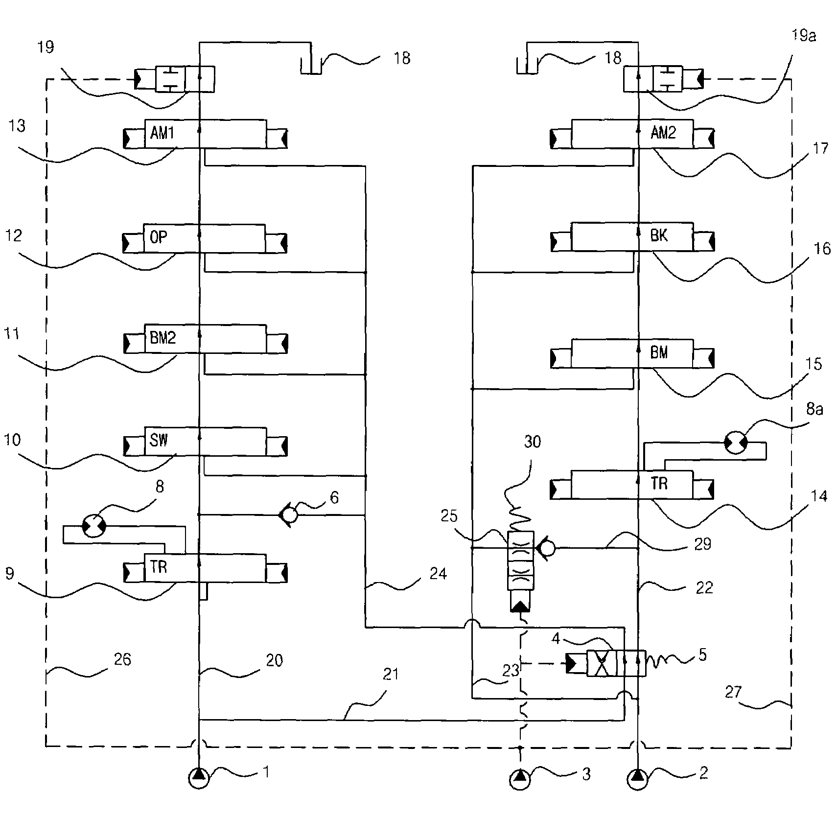
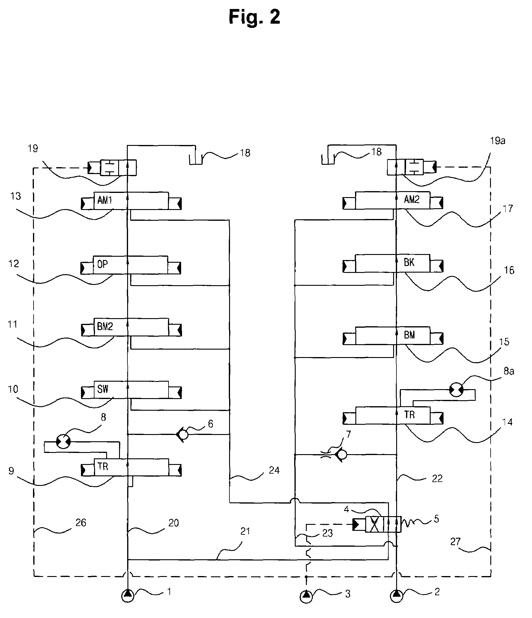
[0041]Referring to FIG. 2, the straight traveling hydraulic circuit according to an embodiment of the present invention includes first and second hydraulic pumps 1 and 2; a first traveling control valve 9 and control valves 10 to 13 for a working device (swing, boom, option device, and arm) which are installed in a first center bypass passage 20 of the first hydraulic pump 1; a first center bypass shifting valve 19 installed on the ...


PUM


Abstract

A straight traveling hydraulic circuit is provided. In case of performing a combined operation in which a fine operation of a working device and a fine traveling of a traveling device are simultaneously required, the straight traveling hydraulic circuit can allow the working device and the traveling device to operate independently, and thus prevent a declination or sudden traveling of the equipment. In case of performing the combined operation by simultaneously operating the traveling device and the working device, first and second center bypass shifting valves installed on the lowermost stream side of first and second center bypass passages are shifted by a pilot signal pressure that shifts a straight traveling valve installed on an upper stream side of the second center bypass passage, so that the degree of opening of the first and second center bypass passages is reduced to operate the working device and the traveling device independently.

Description

CROSS-REFERENCE TO RELATED APPLICATION[0001]This application is based on and claims priority from Korean Patent Application Nos. 10-2006-34747 and 10-2006-34748, filed on Apr. 18, 2006 in the Korean Intellectual Property Office, the disclosure of which is incorporated herein in its entirety by reference.BACKGROUND OF THE INVENTION[0002]1. Field of the Invention[0003]The present invention relates to a straight traveling hydraulic circuit for heavy construction equipment using a plurality of hydraulic pumps, which can improve the traveling manipulability of the equipment during a combined operation in which a traveling operation and a working operation are simultaneously performed.[0004]More particularly, the present invention relates to a straight traveling hydraulic circuit, which, in case of performing a combined operation in which a fine operation of a working device and a fine traveling of a traveling device are simultaneously required, such as burying of waste pipes under a road...

Claims


Application Information

Patent Timeline
Patent Type & Authority Patents(United States)
IPC IPC(8): F15B11/00B62D11/06
CPCB62D11/005E02F9/2239E02F9/225E02F9/2253E02F9/2282E02F9/2285F15B11/17E02F9/2292F15B2211/782F15B2211/20576F15B2211/20584F15B2211/20592F15B2211/3116F15B2211/7142
Inventor KIM, JIN WOOK
Owner VOLVO CONSTR EQUIP HLDG (SWEDEN) AB
Why Eureka
Try Eureka