Device employing gas generating cell for facilitating controlled release of fluid into ambient environment

a technology of gas generation cell and fluid, which is applied in the direction of lighting and heating apparatus, combustion types, instruments, etc., can solve the problems of not being able to pass through the impermeable member and not being able to allow gas

Inactive Publication Date: 2009-11-10
MICROLIN
View PDF97 Cites 21 Cited by
  • Summary
  • Abstract
  • Description
  • Claims
  • Application Information

AI Technical Summary

Benefits of technology

[0013]The third compartment has an opening in the bottom of the device. The third compartment contains a small initial amount of fluid. This compartment is sealed at the bottom opening by metal or plastic. The user of the device breaks the seal to get initial instant dose of fluid on to the emanator system to be volatilized into a surrounding atmosphere. The container of the device is positioned such that the first compartment is above second compartment and second compartment is above third compartment to allow gravity to help effectuate delivery of the fluid.

Problems solved by technology

The impermeable member does not allow any fluid or its vapors within the second compartment to reach first compartment.
It also does not allow gas generated by the gas generative cell to permeate into second compartment until such time that the pressure generated by the gas breaks the seal of the member and allows gas to put pressure on the fluid in second compartment.

Method used


Image

  • Device employing gas generating cell for facilitating controlled release of fluid into ambient environment
  • Device employing gas generating cell for facilitating controlled release of fluid into ambient environment
  • Device employing gas generating cell for facilitating controlled release of fluid into ambient environment

Examples


Embodiment Construction

[0024]While the present invention is capable of embodiment in many different forms, there is shown in the drawings, and will herein be described in detail, one or more specific embodiments with the understanding that the present disclosure is to be considered an exemplification of the principles of the invention and is not intended to limit the invention to these specific embodiments.

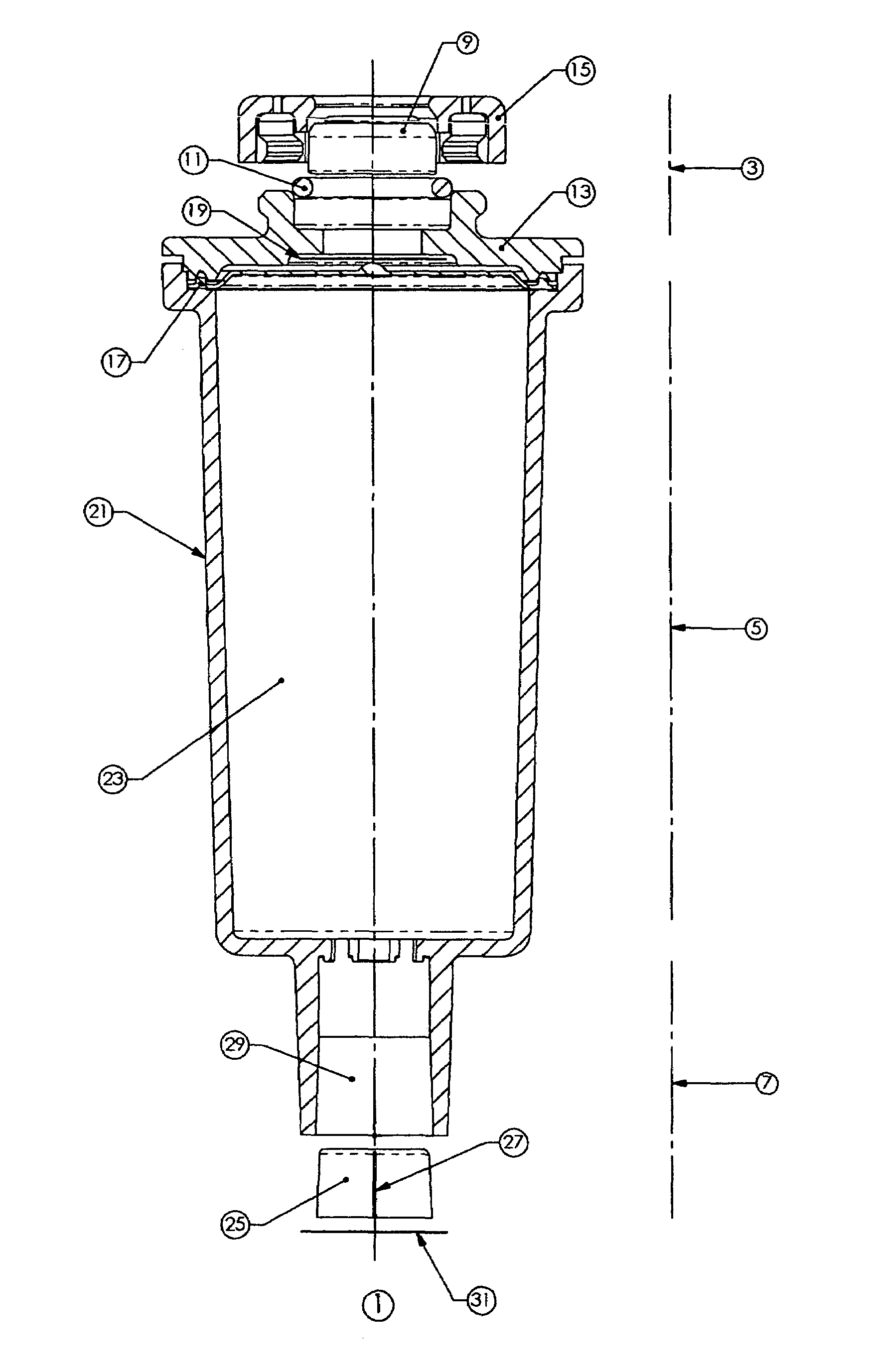
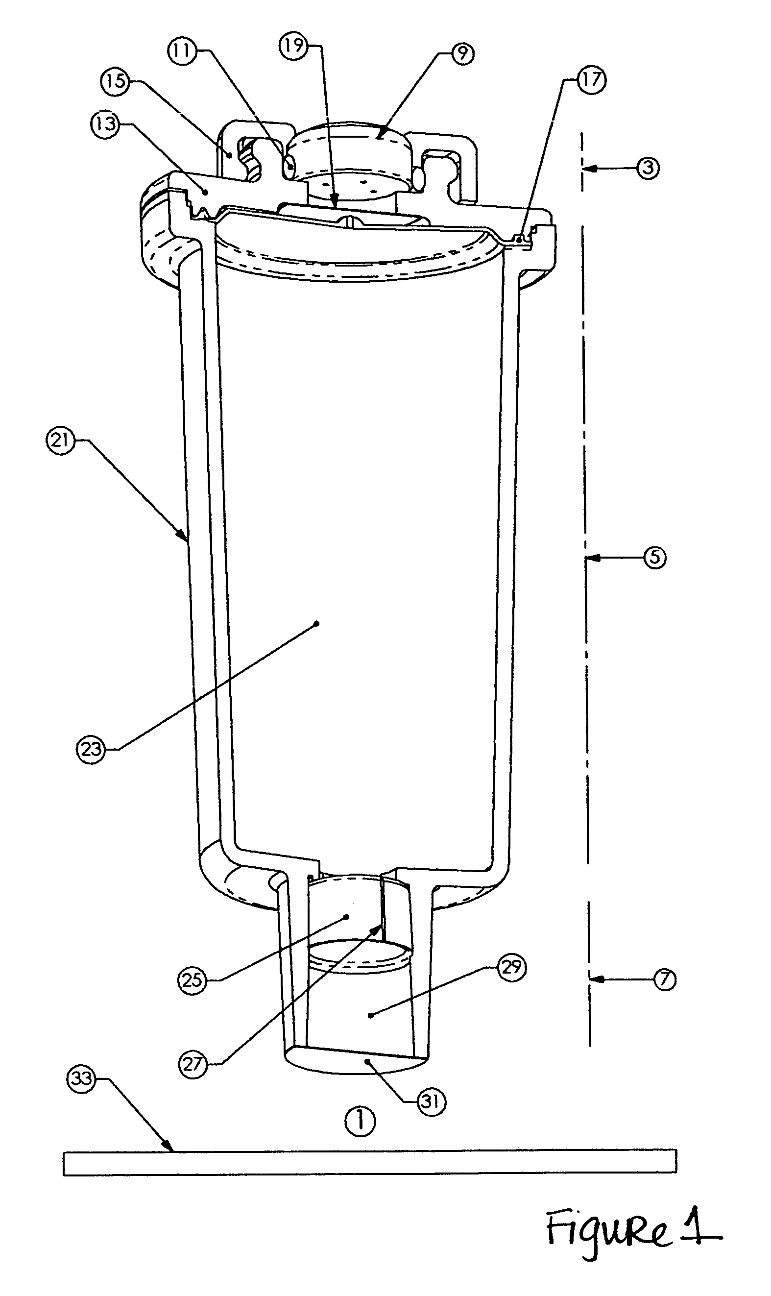
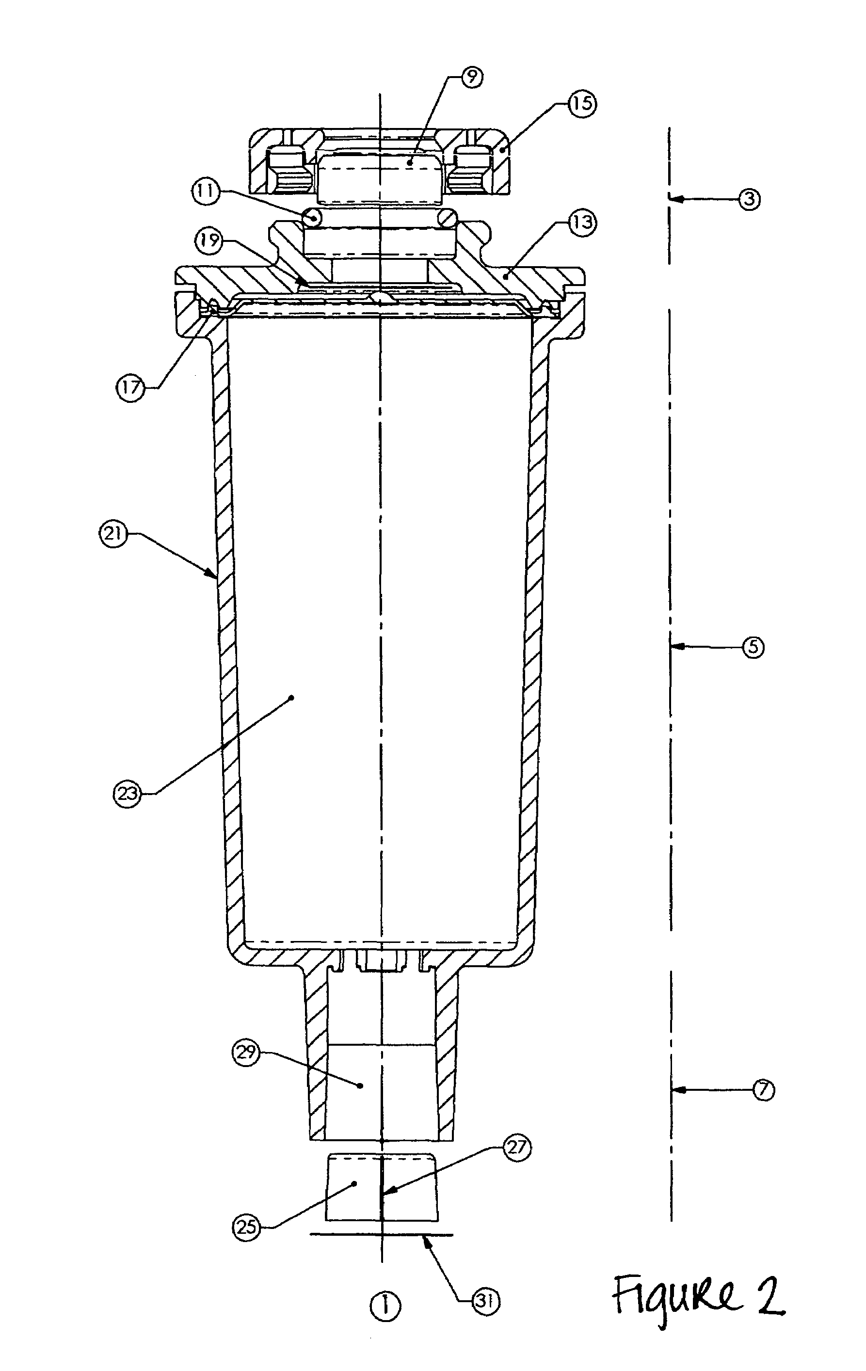
[0025]FIG. 1 depicts a particular embodiment of the device, shown in section view in order to illustrate the details of construction. FIG. 2 shows the preferred embodiment in an exploded section view. In this embodiment, the device has two main components, a fluid delivery container 1 and the emanation system 33. The container 1 is made up of three main sections, the gas generation compartment 3, the fluid compartment 5 and the orifice compartment 7.

[0026]The gas generation compartment 3 features a gas generating cell 9, held within the top cover 13. The top cover 13 is made of a material that is substa...


PUM

PropertyMeasurementUnit
forceaaaaaaaaaa
pressureaaaaaaaaaa
permeableaaaaaaaaaa

Abstract

A device for controllably releasing a fluid into an ambient environment. According to a particular embodiment of the present invention, the device comprises a housing having a fluid compartment and an orifice compartment disposed adjacent thereto and in fluid communication therewith via an orifice. The fluid compartment contains the fluid for release to the ambient environment. The orifice compartment includes a fluid exit opening covered by a removable sealing element and contains an initial quantity of fluid when the device is in an inactivated state. A fluid restrictor is disposed adjacent the orifice to restrict fluid flow from the fluid compartment into the orifice compartment in the inactivated state. A gas-generating cell is in selective communication with the fluid compartment such that gas generated by the cell is directed into the fluid compartment when the device is in an activated state. A fluid membrane is disposed between the gas-generating cell and the fluid compartment that allows the gas generated by the cell to pass therethrough to the fluid compartment in the activated state while preventing fluid within the fluid container from passing therethrough to the cell in the inactivated state. The device is activated by removing the sealing element to allow the initial quantity of fluid to exit out of the orifice compartment via the fluid exit opening and activating the cell to generate gas and force fluid from the fluid compartment to the orifice compartment and out the fluid exit opening in a controlled manner.

Description

CROSS-REFERENCE TO RELATED APPLICATIONS[0001]This application is a continuation-in-part of, and claims priority to, the following applications: application Ser. No. 09 / 645,673, entitled “Controlled Release of Substances,” filed Aug. 24, 2000 now U.S. Pat. No. 6,923,383; application Ser. No. 09 / 649,563, entitled “Controlled Release of Substances,” filed Aug. 28, 2000; application Ser. No. 10 / 115,273, entitled “Electrochemical Cell with Cathode Construction,” filed Apr. 2, 2002 now U.S. Pat. No. 6,787,008; application Ser. No. 10 / 300,729, entitled “Foldable, Refillable Sustained-Release Fluid Delivery System,” filed Nov. 20, 2002 now U.S. Pat. No. 6,957,779; and application Ser. No. 10 / 709,440 entitled “Moving Emanators,” filed May 5, 2004.TECHNICAL FIELD[0002]This invention relates generally to fluid dispensing devices, and more particularly to fluid dispensing devices employing gas-generating cells as a propulsion component to facilitate controlled release of a fluid, such as, for e...

Claims


Application Information

Patent Timeline
Patent Type & Authority Patents(United States)
IPC IPC(8): A61L9/04A61L9/03A61L9/12
CPCA61L9/037A61L9/127A61L9/122
Inventor JOSHI, ASHOK V.WOLD, TRUMANMCEVOY, JOHN J.
Owner MICROLIN
Why Eureka
Try Eureka