Adjustable hinge

a hinge and adjustment technology, applied in the field of hinges, can solve the problems of affecting the the loss of the accurate adjustment of the original position, and the tendency to be dislodged under the weight of the shutter

Active Publication Date: 2009-11-17
ELESA
View PDF17 Cites 21 Cited by
  • Summary
  • Abstract
  • Description
  • Claims
  • Application Information

AI Technical Summary

Problems solved by technology

These known hinges, however, have the drawback of tending to become dislodged under the weight of the shutter, which are often heavy metal cabinet doors, and of hence losing their accurately adjusted original position.
However, it has the serious disadvantage that the adjuster movement may occur in only one predefined direction, which is the one determined by the arrangement of the housing seat, parallel or perpendicular to the hinge axis, at the time of hinge manufacture.
This seriously limits the freedom of movement of the adjuster with respect to the hinge and hence the opportunity for accurate adjustment.
Consequently, the manufacturer is forced to manufacture various types of hinges, which the operator will use at pleasure for any intervention he is going to perform, with evident problems in terms of costs and stocking.
However, it cannot be engaged firmly and securely, since the poly-grooved areas do not match (i.e. they do not interlock in all positions).

Method used


Image

  • Adjustable hinge
  • Adjustable hinge
  • Adjustable hinge

Examples


Embodiment Construction

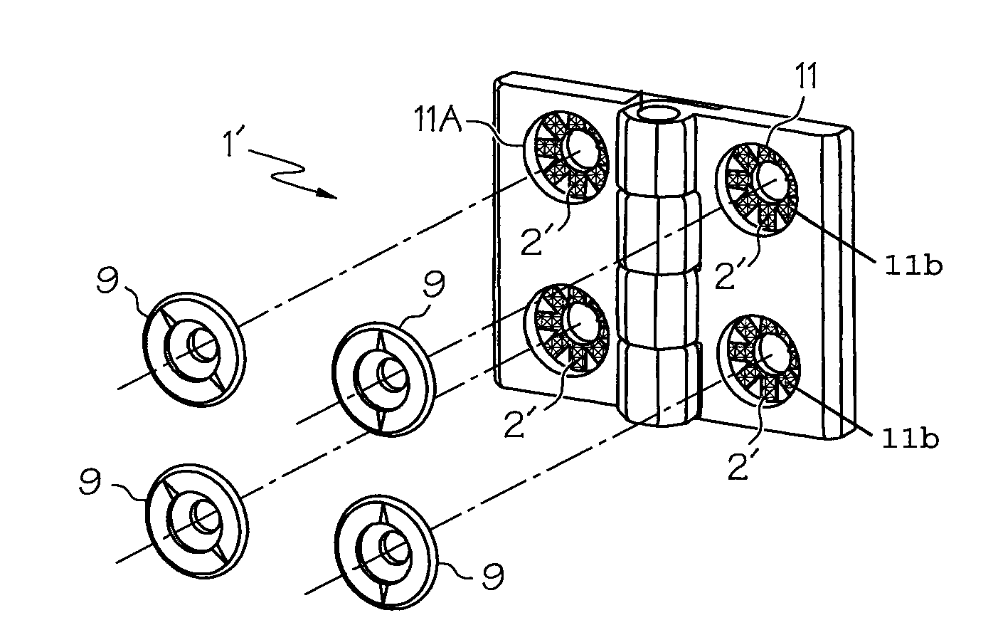
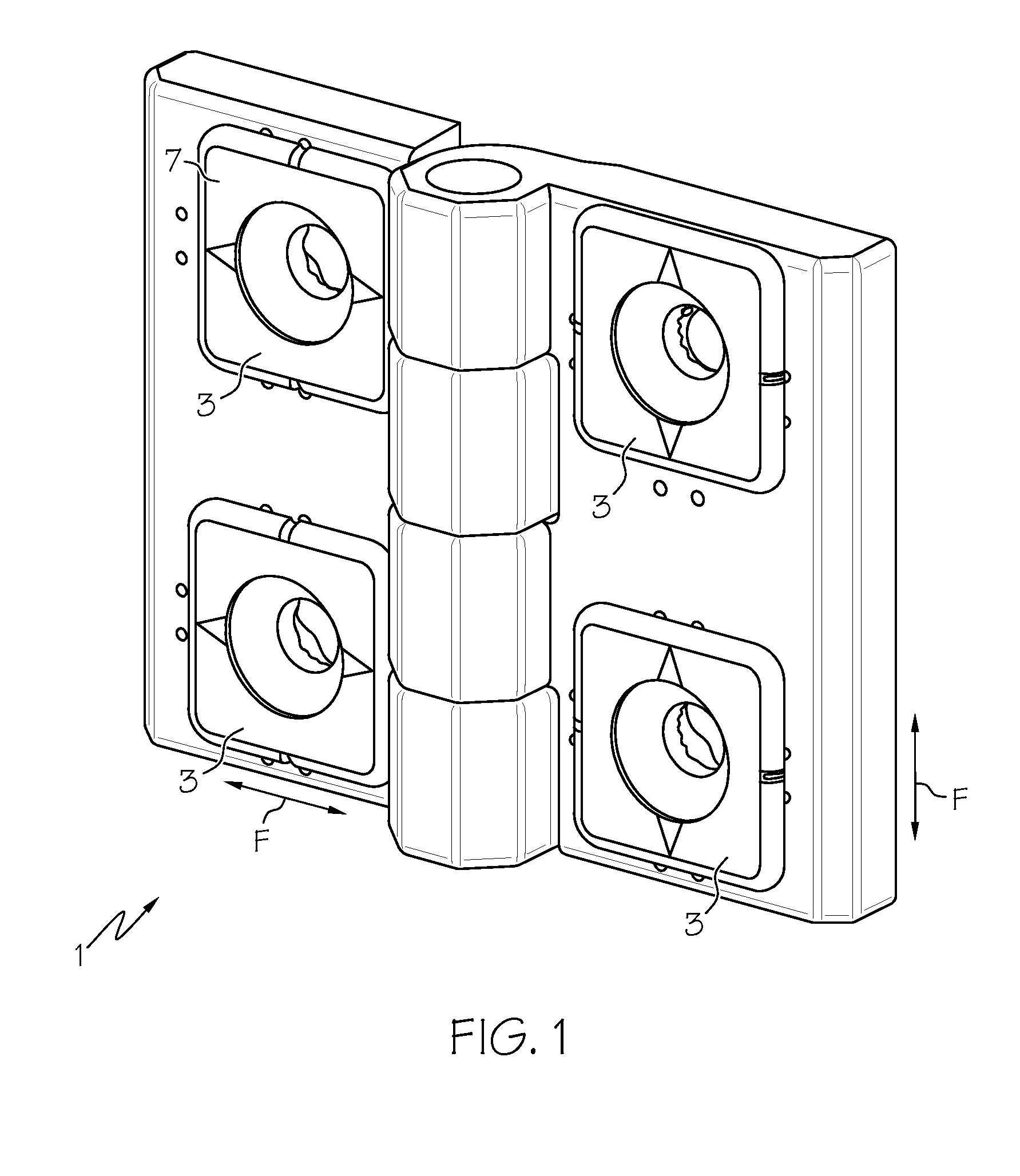
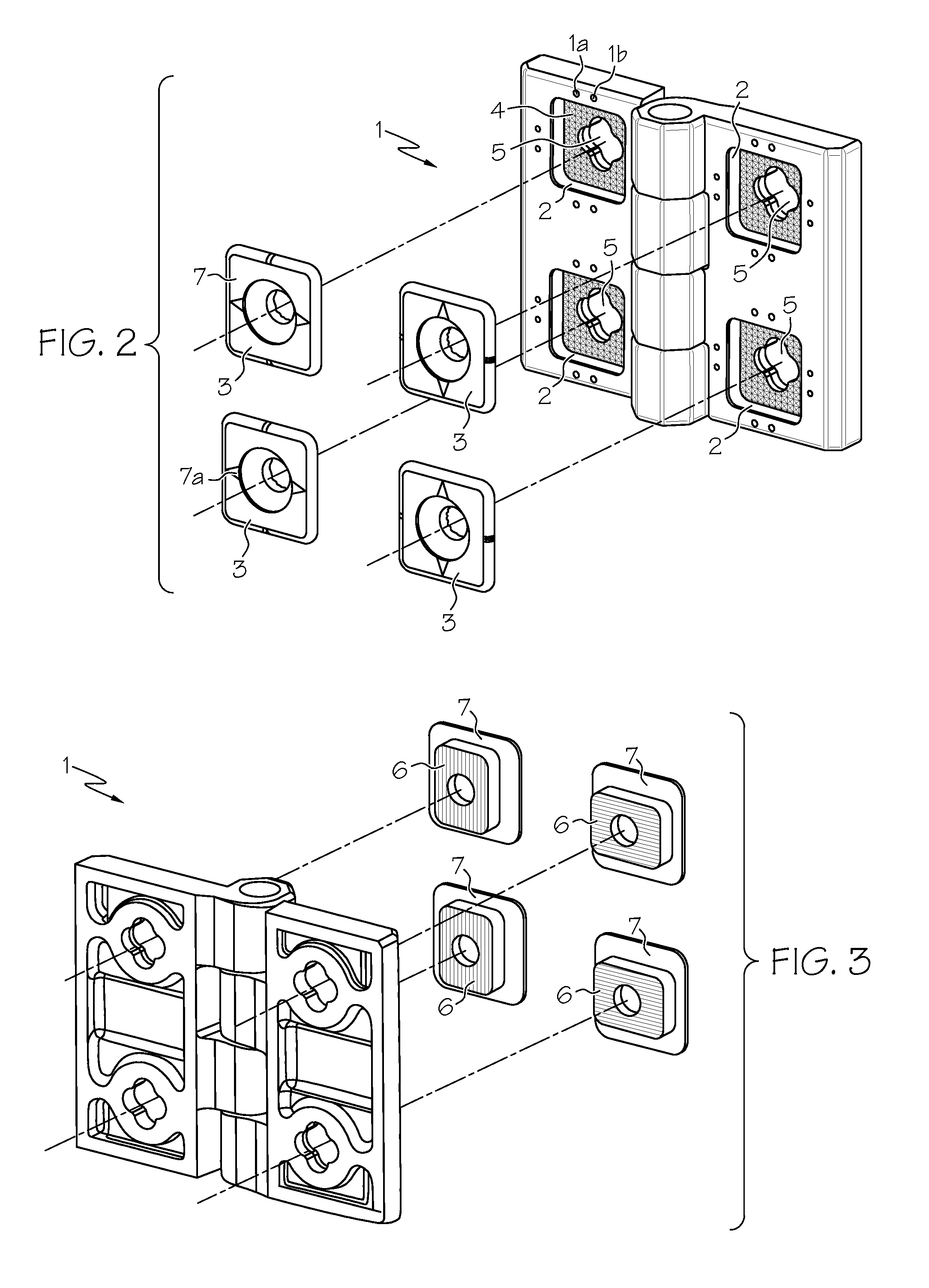
[0021]Certain terminology is used herein for convenience only and is not to be taken as a limitation on the present invention. Further, in the drawings, the same reference numerals are employed for designating the same elements.

[0022]As can be observed from FIGS. 1 to 6, a hinge body 1 can include a pair of hinge flaps connected by a hinge pin or the like on a common pivoting axis to permit rotation of the flaps relative to each other. For example, the flaps can be connected by a hinge pin or the like that can float freely between the two flaps or can even be secured to one of the flaps. As shown, one flap can rotate approximately 270° relative to the other, though various other angles are also contemplated. Additionally, the hinge body 1 and / or the adjusters can be generally molded of a thermoplastic material, such as a technopolymer, but which may be made also of other materials, such as other synthetic materials, rubber, and / or metal. An example technopolymer can include a glass-...


PUM


Abstract

The invention concerns a hinge of the type including of a pair of members of a hinge (1), each having a pair of screw-anchoring holes (5). The holes are obtained within housing seats (2) prearranged for the introduction of adjusters (3, 9). Each adjuster includes a body (6) and a flange (7). The edge of the flange rests on the surface of each member of the hinge (1) in various mutual positions of the adjuster in its respective seat. According to the invention, said housing seats (2) have a centered-symmetry base layout, and guiding means (6, 11, 11a) are provided for guiding said adjuster body (6) into its respective housing seat (2) so as to allow the free movement of the adjuster (3, 9) in a single direction, among multiple possible directions, depending on the orientation of each adjuster (2) in its respective seat.

Description

RELATED APPLICATIONS[0001]This application claims the benefit of Italian application, MI2006U 000041, filed on Jan. 12, 2006, the entire disclosure of which is hereby incorporated herein by reference.FIELD OF THE INVENTION[0002]The present invention relates generally to a hinge, and more particularly to a hinge having adjuster elements for a fastener.BACKGROUND OF THE INVENTION[0003]During the installation of hinges on shutters of doors and machinery, such as access doors or the like, an operator can often find he has to adjust the relative position of the fasteners, such as anchoring screws or the like, with respect to the hinge axis. Such a need may arise for example when, during mounting, it is necessary to compensate for drilling mistakes, minimal misalignments, and / or angular positions of the shutter with respect to the frame post. In any case, there may be various other cases in which precise and secure hinge adjustment becomes a necessity.[0004]Thus, various devices have been...

Claims


Application Information

Patent Timeline
Patent Type & Authority Patents(United States)
IPC IPC(8): E05D7/04
CPCE05D7/04E05D5/04E05D5/023E05Y2600/51Y10T16/5321Y10T16/535Y10T16/554Y10T16/5329E05Y2900/208
Inventor FRANCHINI, GIAN CARLO
Owner ELESA
Why Eureka
Try Eureka