Supercharge Your Innovation With Domain-Expert AI Agents!

Vehicle shock absorber

a technology for shock absorbers and vehicles, applied in the field of vehicle shock absorbers, can solve the problems of difficult to obtain desired shock absorption properties, difficult to provide substantially vertical recessed ribs in the shock receiving surface by blow-molding,

Inactive Publication Date: 2009-11-17
KYORAKU CO LTD
View PDF29 Cites 24 Cited by
  • Summary
  • Abstract
  • Description
  • Claims
  • Application Information

AI Technical Summary

Benefits of technology

The present invention provides a vehicle shock absorber that has a uniform shock absorbing property in all positions of the shock receiving surface. This is achieved by forming a hollow structure with a first and second wall, and a shock receiving surface that connects the walls. The first and second walls are provided with recessed grooves that are formed by walls that are perpendicular to the shock receiving surface. The recessed grooves are formed from an end of the shock receiving surface of the first or second wall to the other end. The recessed grooves in the second wall are positioned alternately with those in the first wall. The shock receiving surface is also formed with semi-arc notches formed by the recessed grooves in the first and second walls, and a parting line is formed between the notches. The vehicle shock absorber can be interposed between a bumper beam and a bumper facia, with the shock receiving surface disposed on the side of the bumper facia.

Problems solved by technology

In the conventional vehicle shock absorbers described in the above patent documents, when the shock receiving surface is small, it is difficult to form recessed ribs in the shock receiving surface.
In addition, when the shock absorber is long in the shock direction, it is difficult to form the recessed rib in the shock receiving surface, and thus a desired shock absorbing property can not be obtained.
Thus, not only when the shock receiving surface of the vehicle shock absorber is small and the shock absorber is long in the shock direction, but also when an area of a first or second wall is wider than an area of the shock receiving surface, it is difficult to provide a substantially vertical recessed rib in the shock receiving surface by blow-molding.
Even if the recessed rib could be formed, position where the recessed ribs are formed is limited, many recessed ribs can not be formed, or the recessed ribs are expanded at the time of forming and the ribs become thin, so that the desired shock absorbing property can not be obtained in some cases.

Method used


Image

  • Vehicle shock absorber
  • Vehicle shock absorber
  • Vehicle shock absorber

Examples


Embodiment Construction

[0023]The present invention will be explained in detail with reference to the accompanying drawings.

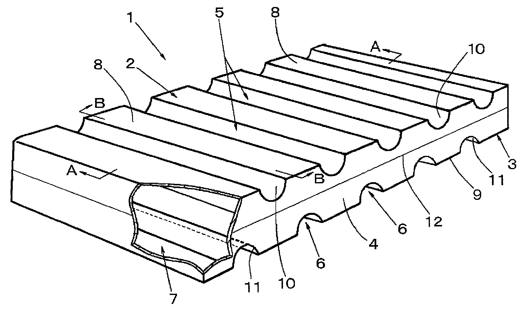
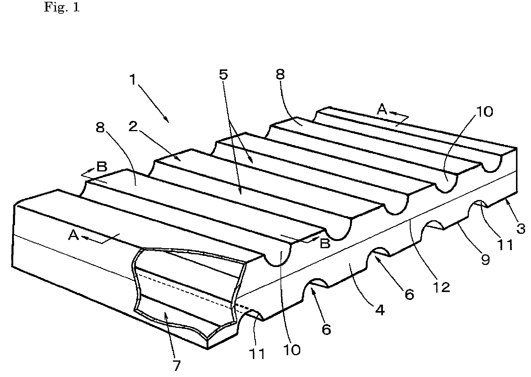
[0024]In FIGS. 1 to 3, a reference symbol 1 represents a vehicle shock absorber. The vehicle shock absorber 1 is formed to be hollow by blow-molding thermoplastic plastic, and a first wall 2 and a second wall 3 are opposed to each other at a distance from each other. A peripheral wall connecting one ends of the first wall 2 and the second wall 3 functions as a shock receiving surface 4. The first wall 2 and the second wall 3 are formed with a plurality of recessed grooves 5 and 6 arranged at substantially equal distances from each other. A reference symbol 7 represents a hollow portion.

[0025]In the shock absorber 1, an area of the shock receiving surface 4 is smaller than an area of the first wall 2 or the second wall 3. The shortest distance from a contact point between the shock receiving surface 4 and the first wall 2 to a contact point between the shock receiving surface 4 and the...


PUM


Abstract

A vehicle shock absorber by which a uniform shock absorbing property can be obtained in all positions on a shock receiving surface and, particularly, a further uniform shock absorbing property can be obtained if the distance from the lower end of a recessed groove in a first wall to a second wall is made equal to the distance from the lower end of the recessed groove in the first wall to the lower end of a recessed groove in the second wall. A vehicle shock absorber (1) is installed inside a vehicle component part so as to absorb shocks from interior or exterior. The vehicle shock absorber (1) is formed hollow by blow-molding thermoplastic plastic. A first wall (2) and a second wall (3)are spaced from and opposed to each other. A shock receiving surface (4) connects the first and second walls (2, 3). The first and second walls (2, 3) are formed with pluralities of recessed grooves (5, 6) at substantially equally spaced intervals. The recessed grooves (5, 6) are disposed substantially normal to the shock receiving surface (4).

Description

RELATED APPLICATION[0001]This application is a 35 U.S.C. 371 national phase application of PCT Application Ser. No. PCT / JP2004 / 016892, filed 8 Nov. 2004,which claims priority to Japanese Application No. 2003-399874, filed 28 Nov. 2003. Each of these application is herein incorporated in its entirety by reference.[0002]1. Technical Field[0003]The present invention relates to a vehicle shock absorber, provided inside a vehicle structural member such as a door, a body side panel or a bumper facia, for absorbing the shock from the inside such as the collision of a passenger against the inner wall of the vehicle structural member or the shock from the outside such as the collision or contact with another vehicle or other objects.[0004]2. Background Art[0005]As the vehicle shock absorber of this kind, the following absorbers are known. That is, vehicle bumpers each having a blow-molded bumper core (vehicle shock absorber) which are disposed on left and right portions inside of a bumper fa...

Claims


Application Information

Patent Timeline
Patent Type & Authority Patents(United States)
IPC IPC(8): B60R19/18B60R19/03B60R21/04
CPCB60R19/18B60R21/04B60R2021/0435B60R2019/188B60R21/0428
Inventor TAMADA, TERUO
Owner KYORAKU CO LTD
Features
  • R&D
  • Intellectual Property
  • Life Sciences
  • Materials
  • Tech Scout
  • Unparalleled Data Quality
  • Higher Quality Content
  • 60% Fewer Hallucinations
Learn More