Irradiance-redistribution lens and its applications to LED downlights

a technology of irradiance-redistribution and led downlight, which is applied in the direction of instruments, lighting and heating apparatus, semiconductor devices for light sources, etc., can solve the problems of expensive and bulky projection lamps that cannot produce square light beams, and conventional led optics that do not provide uniform output and high directionality for led downlights

Active Publication Date: 2009-11-17
SINOTECHNIX LLC
View PDF10 Cites 82 Cited by
  • Summary
  • Abstract
  • Description
  • Claims
  • Application Information

AI Technical Summary

Benefits of technology

[0007]One preferred embodiment of this new lens produces a very tightly collimated beam with uniform irradiance. This is advantageous for LED downlights because different diffuser-covers can go across this beam to produce a variety of circular or elliptical beam patterns, albeit with fuzzy boundaries.

Problems solved by technology

Conventional LED optics, however, provide neither uniform output nor the high directionality required for a downlight to produce, for example, a small spot of light on a table.
Currently only expensive and bulky projection lamps can produce a square light beam, and quite inefficiently at that, by using large lenses to form an image of a square aperture placed in the output beam of a collimating lens or mirror that uses an incandescent lamp.

Method used


Image

  • Irradiance-redistribution lens and its applications to LED downlights
  • Irradiance-redistribution lens and its applications to LED downlights
  • Irradiance-redistribution lens and its applications to LED downlights

Examples


Embodiment Construction

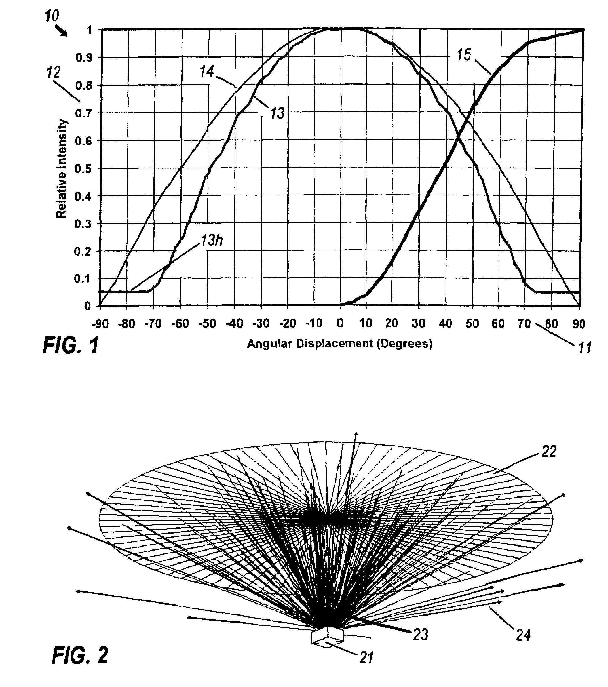
[0031]A Lambertian light source presents constant luminance at all angles, so that off-axis foreshortening of its flat output aperture gives a cosine dependence of intensity. Actual LED chips can differ from this ideal pattern. FIG. 1, as an example, shows intensity graph 10 with horizontal angular scale 11 and vertical scale 12 showing relative intensity. Curve 13 is the measured output of the Flash-LED made by the Lumileds Corporation. For comparison, curve 14 graphs the cosine dependence of a perfectly Lambertian emitter, showing that curve 13 may be called ‘sub-Lambertian’, in spite of horizontal branch 13h. This latter feature is due to lateral leakage out of the top of the Flash package.

[0032]An important feature of an intensity distribution is the cumulative flux distribution, defined as the normalized angular integral of the intensity I(θ):

J(ψ)=0┌ψI(θ)sin θdθ / 0┌90I(θ)sin θdθ

Curve 15 graphs this function, showing that 90% of the flux lies within 63° of the axis, a solid angle...


PUM


Abstract

An illumination-redistribution lens comprising a thick aspheric lens collecting a high proportion of the luminous output of a compact LED with a quasi-hemispheric pattern. After receiving the highly nonuniform illuminance from the nearby LED, the lower surface refractively deflects these rays into a less diverging angular pattern that results in uniform illuminance on the upper surface of the lens, which itself is shaped so its distribution of slope angles refractively deflects the uniform illuminance distribution into an exiting beam that will produce uniform illuminance on a distant target, such as a table below a ceiling-mounted unit. When square-cut sections of such lenses are laterally arrayed to form a downlight, a uniform rectangular spot will be produced on the target.

Description

[0001]This application is based on provisional application Ser. No. 60 / 627,287 filed Nov. 12, 2004.BACKGROUND OF THE INVENTION[0002]Illumination lenses act to collect light from a source and gather it into a useful beam to cast upon a target. Frequently, uniform illumination is desired, but most often not attained. Sometimes this is because the target, such as a room's floor, has widely varying distance and slant to the luminaire, so that uniform intensity becomes nonuniform illumination. In most cases, though, the luminaire itself has widely varying distance from its light source to its different light-redirecting sections. Thus both mirrors and lenses typically have nonuniform illumination across their exit apertures. The present invention addresses this problem with a general method of making a lens achieve uniform exit-aperture irradiance as well as uniform target irradiance. This capability is particularly important for the next generation of high-brightness light-emitting diod...

Claims


Application Information

Patent Timeline
Patent Type & Authority Patents(United States)
IPC IPC(8): F21V5/04
CPCG02B19/0014G02B19/0061G02B27/0955F21V5/002F21V5/04F21Y2101/02Y10S362/80F21Y2115/10
Inventor PARKYN, WILLIAM A.PELKA, DAVID G.
Owner SINOTECHNIX LLC
Why Eureka
Try Eureka