Method and apparatus for producing a uniform irradiance distribution from an array of light emitting diodes

a technology of light-emitting diodes and arrays, which is applied in lighting and heating apparatus, instruments, condensers, etc., can solve the problems of large cost, large cost, and the use of relatively expensive yag lasers for sensors, and achieves the effect of increasing power excitation energy

Active Publication Date: 2013-04-30
NORTHROP GRUMMAN SYST CORP
View PDF14 Cites 0 Cited by
  • Summary
  • Abstract
  • Description
  • Claims
  • Application Information

AI Technical Summary

Benefits of technology

[0011]The method and apparatus of the exemplary embodiments may allow higher power excitation energy for fluorescence sensing while providing relatively uniform irradiance of particles passing therethrough. The uniformity of illumination provides a relatively repeatable signal for target particles, and for background particles that might interfere with detections of the target particles.

Problems solved by technology

One drawback of using these sensors deals with the large costs involved.
For instance, these sensors typically rely on relatively expensive YAG lasers and photomultiplier tube (PMT) optical detectors, and may cost $40,000 to $100,000.
However, one disadvantage of using current UV LEDs operating at a wavelength of 280 nanometers is that the LED output power in current devices is about a factor of 10 or more lower than what is desired for good sensitivity of the sensor.
However, inputting more electrical current to the LED junction results in an increase in the thermal load and a consequent reduction in the lifetime of the LED.
Increasing the emitting area of the diode of an LED may help to distribute the thermal load, but typically results in current depletion in regions of the emitting area that lead to unacceptable non-uniformity in the projected spot distribution.
Since these are competing performance parameters, there is always a trade-off of power for uniformity.

Method used


Image

  • Method and apparatus for producing a uniform irradiance distribution from an array of light emitting diodes
  • Method and apparatus for producing a uniform irradiance distribution from an array of light emitting diodes
  • Method and apparatus for producing a uniform irradiance distribution from an array of light emitting diodes

Examples


Embodiment Construction

[0019]The present invention now will be described more fully hereinafter with reference to the accompanying drawings, in which some, but not all embodiments of the inventions are shown. Indeed, these inventions may be embodied in many different forms and should not be construed as limited to the embodiments set forth herein; rather, these embodiments are provided so that this disclosure will satisfy applicable legal requirements. Like numbers refer to like elements throughout.

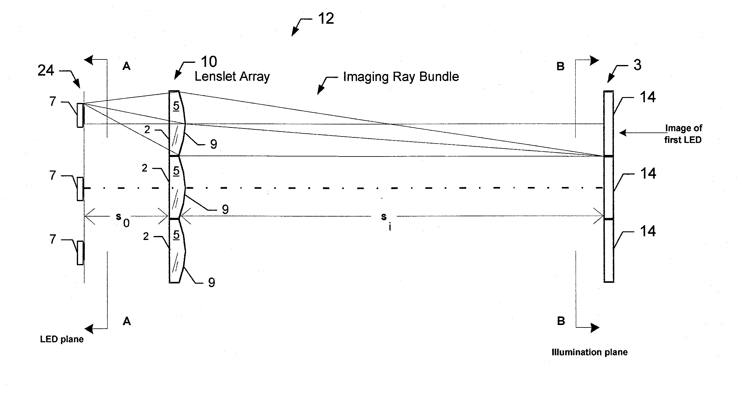
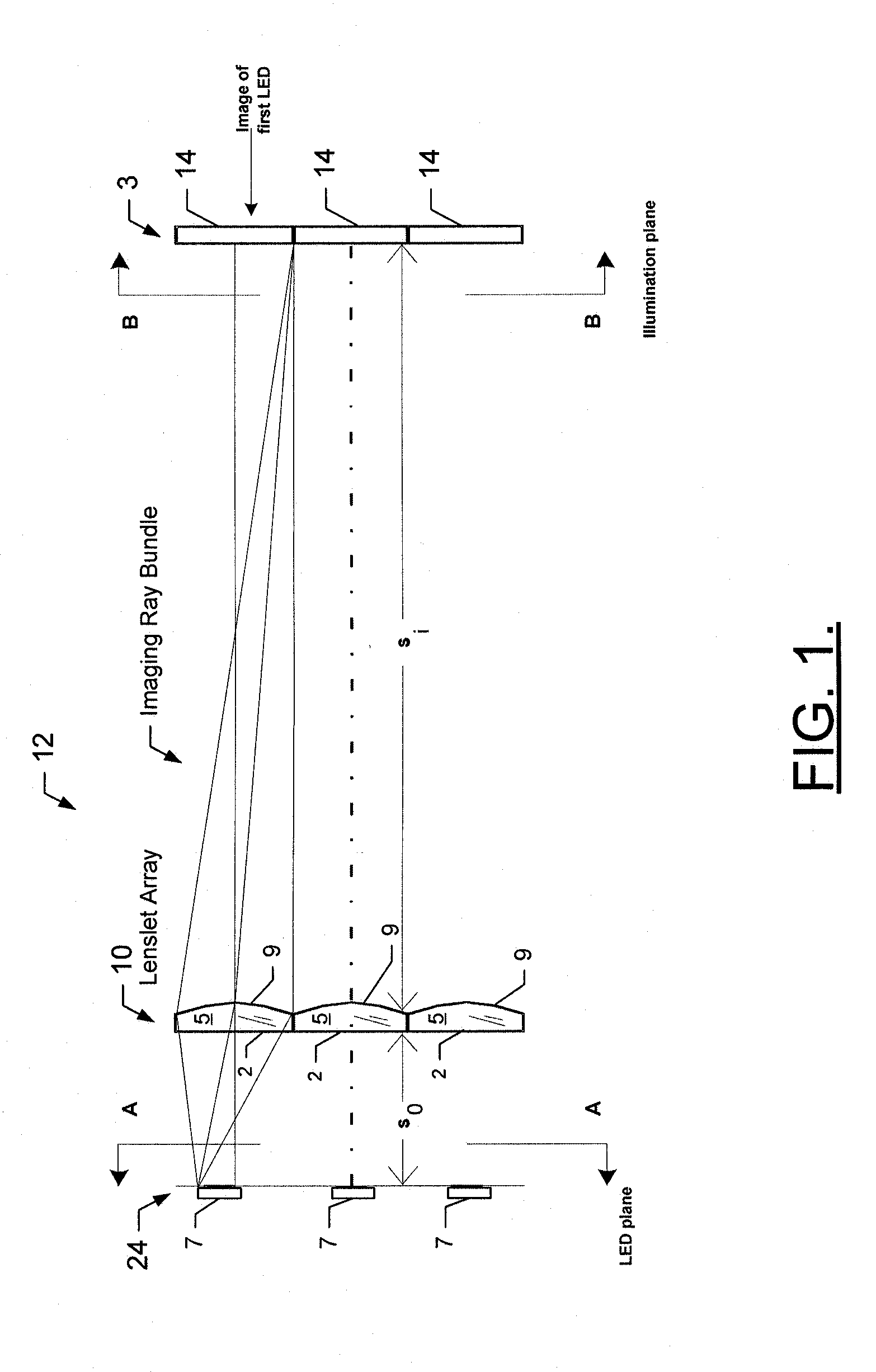
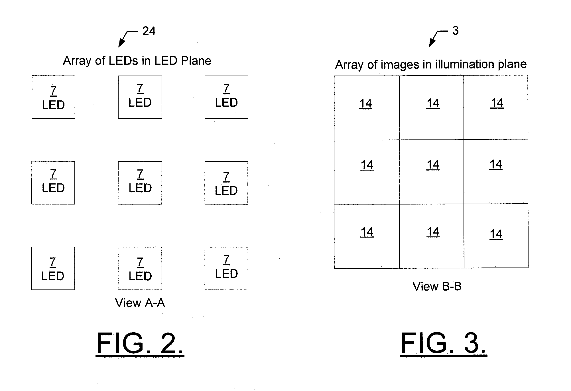
[0020]Referring now to FIG. 1, a diagram of an imaging apparatus for producing a uniform irradiance distribution in an illumination plane is provided. The imaging apparatus 12 includes LEDs 7 in an LED array 24 (see FIG. 2, which shows a front view of the LED array 24), lenslets 5 in a lenslet array 10, and an illumination plane 3. As can be seen in FIG. 2, the LED array 24 includes a plurality of LEDs 7 arranged in a plurality of rows and columns in the same plane. In this exemplary embodiment, the LED array 2...


PUM


Abstract

An apparatus and method for producing a spatially uniform irradiance in an image plane are provided. The apparatus includes an array of light emitting diodes (LEDs) which generate light (i.e., an image). The apparatus combines the outputs of an array of the LEDs in such a way as to produce a spatially uniform irradiance in an image plane some distance away. The apparatus includes an array of lenslets to form images of the emitting areas of the individual LEDs. The lenslets have a magnification, size and spacing such that the images produced by the respective LEDs are adjacent to one another and not overlapping. The irradiance distribution in the image plane is equivalent to an image of an LED whose emitting area is equal to the total area of the LED array, and whose total power is equal to the total power of the LEDs in the LED array.

Description

FEDERALLY SPONSORED RESEARCH OR DEVELOPMENT[0001]This invention was made with United States Government support under contract number HSHQDC-06-C-0028, and under contract number Low-Cost Bio-Aerosol Detection Systems (LBADS) 19069 both awarded by the U.S. Department of Homeland Security. The United States Government has certain rights in the invention.FIELD OF THE INVENTION[0002]Embodiments of the present invention relate in general to light emitting diodes (LEDs) and more particularly, to a method and apparatus for producing a uniform irradiance distribution from an array of light emitting diodes by using an array of lenslets to form images of the emitting areas of the individual LEDs in the array, or to form images of the ends of bundled fiber optics that are transmitting LED illumination, in a manner to generate a spatially contiguous and / or uniform irradiance.BACKGROUND OF THE INVENTION[0003]LEDs are used in a wide variety of applications and are being considered for even additio...

Claims


Application Information

Patent Timeline
Patent Type & Authority Patents(United States)
IPC IPC(8): F21V5/00
CPCG02B27/0961G02B19/0066G02B19/0095G02B19/0014
Inventor GIGIOLI, JR., GEORGE WILLIAM
Owner NORTHROP GRUMMAN SYST CORP
Why Eureka
Try Eureka