Super thin reflective projection display imaging method and objective lens based on free camber

An imaging method and projection display technology, applied in optical components, optics, instruments, etc., can solve problems such as difficult simultaneous correction, increase of field of view, improvement of imaging objective lens, etc., to ensure imaging clarity, eliminate the influence of chromatic aberration, Effect of Correcting Aberrations

Inactive Publication Date: 2009-01-07
ZHEJIANG UNIV
View PDF10 Cites 1 Cited by
  • Summary
  • Abstract
  • Description
  • Claims
  • Application Information

AI Technical Summary

Problems solved by technology

Therefore, the overall development trend of imaging objective lens is short focal length, large field of view, large relative aperture and high definition, which makes the design and production of imaging objective lens more difficult. With the increase of the field of view and the relative aperture, various chromatic aberrations, off-axis aberrations, and distortions will change rapidly, and it is difficult to correct them at the same time. In order to meet the performance requirements, it is necessary to continuously propose new imaging objective lens structures, or for The structure of the imaging objective lens is complicated, so the structure of the transmission imaging objective lens will become more and more complex and have certain limitations.
The design concept of reflective imaging objective lens has been paid more and more attention. At present, reflective imaging objective lens is mostly designed with the structure of even-order aspheric surface. In the case of a short projection distance, it will cause an increase in the angle of view and various chromatic aberrations. At the same time, in the case of a short focal length and a large field of view, it is still difficult to correct the aberrations at the same time, and it is difficult to ensure the imaging clarity. When the spherical surface has a large surface shape, there are certain difficulties in processing and surface shape measurement. With the rapid progress of processing and testing technology in recent years, the free-form surface has developed rapidly. The aspheric surface has greater design freedom, so it can better correct various aberrations such as spherical aberration and coma, obtain better imaging quality, and make it possible to simplify the structure and reduce costs

Method used


Image

  • Super thin reflective projection display imaging method and objective lens based on free camber
  • Super thin reflective projection display imaging method and objective lens based on free camber
  • Super thin reflective projection display imaging method and objective lens based on free camber

Examples


Embodiment Construction

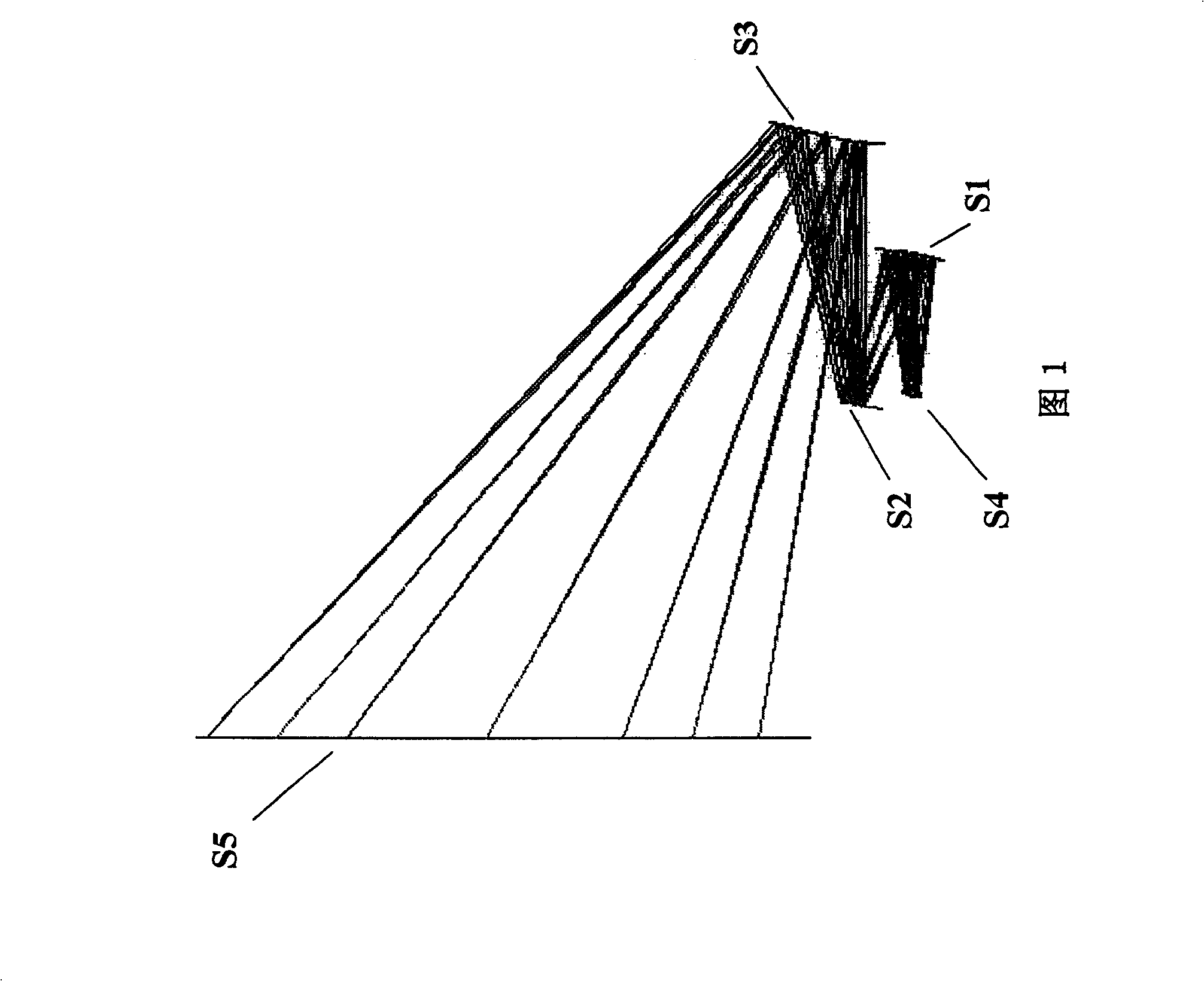
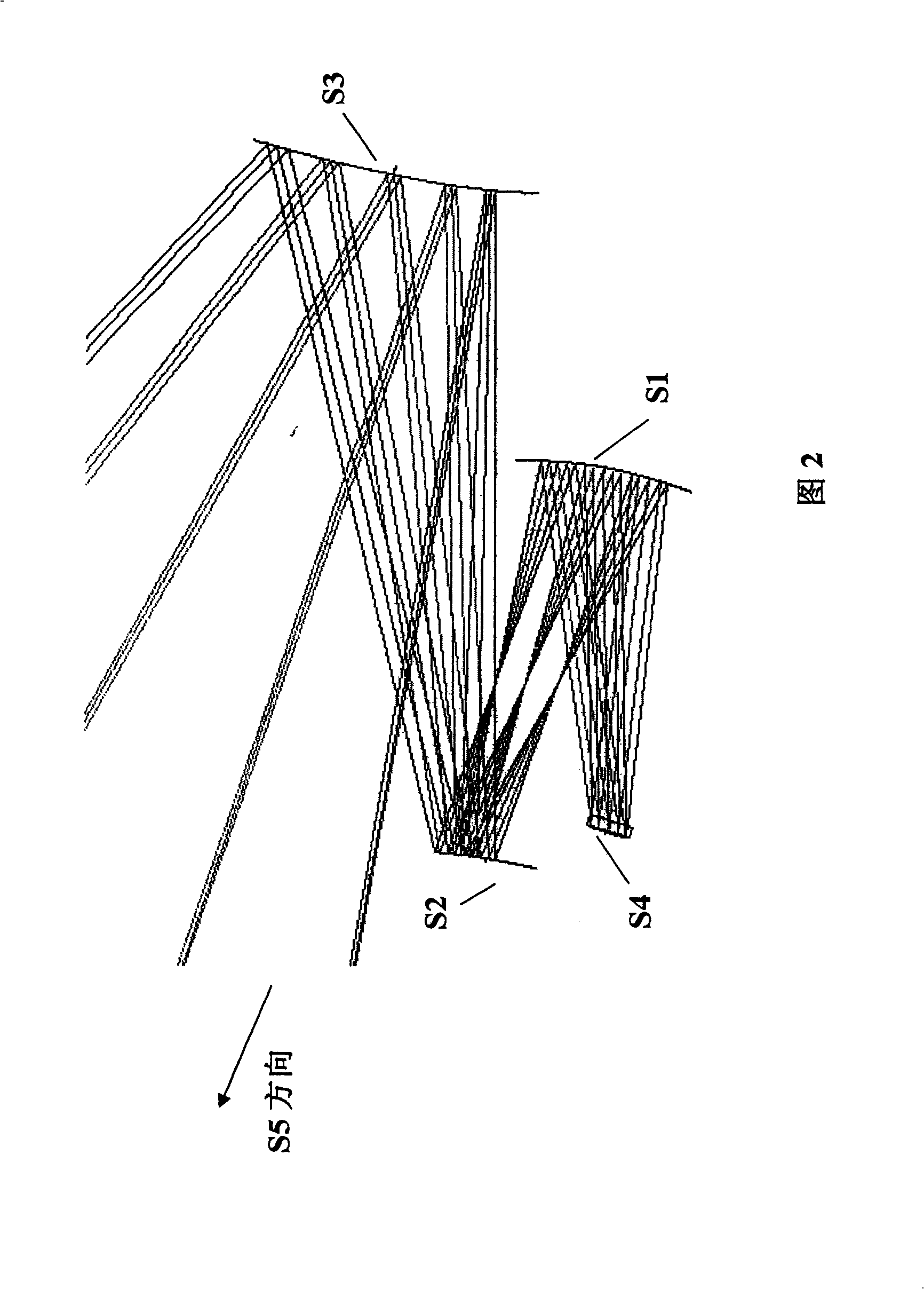
[0033] Ultra-thin reflective projection display imaging methods based on free-form surfaces include:

[0034] 1) The concave reflective surface S1 used to correct the spherical aberration and coma aberration caused by off-axis reflection, the convex reflective surface S2 used to correct the off-axis aberration caused by the large relative aperture and off-axis, and the convex reflective surface S2 used to correct the off-axis produced The reflective structure of the distorted convex reflective surface S3, the concave reflective surface S1, the convex reflective surface S2, and the convex reflective surface S3 use Zernike polynomial free-form surfaces to correct aberrations;

[0035] 2) The distance between each reflective surface is extended by using multiple folded reflections and off-axis methods, and the overall projection imaging distance is shortened by extending the distance between reflective surfaces;

[0036] 3) Reflective imaging with short focal length, large relati...


PUM


Abstract

This invention discloses a kind of extra-thin reflection type projected display imaging method based on free curved surface and object lens. It has concave catopter, convex catopter, convex catopter, object plane and image surface in proper order. The merit of the invention are: 1) adopting free curved surface imaging method , three part reflection type Zernike polynomial free curved surface forms short focal distance bigger, relative apertures bigger fields of view angle imaging , rectifying optical aberration much better and its structure is simple; 2) adopting the reflection structure without optical lens, has removed the effect of various chromatic aberration , guarantee the imaging articulation; 3) adopt the design of short focal distance big fields of view angle, focal distance 8 - 15 mm, field of view angles 100 -135 degree, having 120 times multiplications under 250 mm imaging distance, having ultra-thin characteristic property; 4) adopting big relative apertures design ,the relative aperture is 2.0-2.4, having improved the illuminance of flat surface; 5) adopting image space telecentric imaging method , ensures that the image surface irradiance is homogeneous.

Description

technical field [0001] The invention relates to an ultra-thin reflective projection display imaging method and an objective lens based on a free-form surface. Background technique [0002] Projection display technology has developed rapidly in recent years. Large screen and high-definition image display are the main advantages of projection display, and its small size and light weight can be widely used in audio-visual teaching, office, business, advertising and entertainment. The prospects are broad. According to the different display devices used, the projection display technologies currently used include DMD, LCD, and LCoS projection display. The projection display uses the digital signal or other video signal generated by the computer to form an image source on the display device through the driving circuit. Through the lighting system, the After the light emitted by the light source is modulated by the display device, it is enlarged and imaged by the projection imaging...

Claims


Application Information

Patent Timeline
Patent Type & Authority Patents(China)
IPC IPC(8): G02B27/00G02B13/00
Inventor 郑臻荣孙旭涛李海峰刘旭顾培夫
Owner ZHEJIANG UNIV
Why Eureka
Try Eureka