
Method and apparatus for forming concrete blocks

a concrete block and casting method technology, applied in the field of casting concrete blocks, can solve the problems of difficult to manufacture large concrete blocks with highly irregular surfaces, block not easily released from the form, and add to the cost of manufacturing blocks

Active Publication Date: 2009-11-17
ROSETTA HARDSCAPES
View PDF8 Cites 49 Cited by
  • Summary
  • Abstract
  • Description
  • Claims
  • Application Information

AI Technical Summary

Benefits of technology

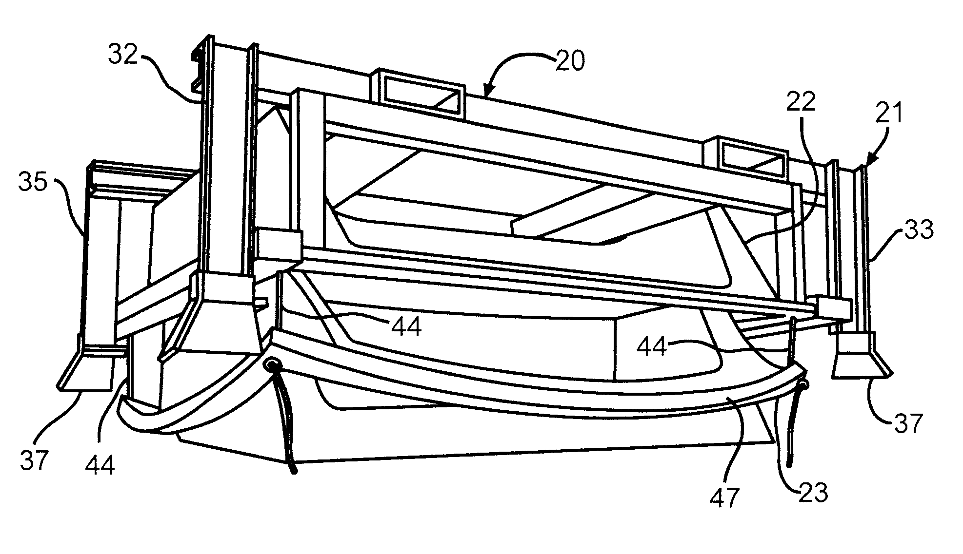
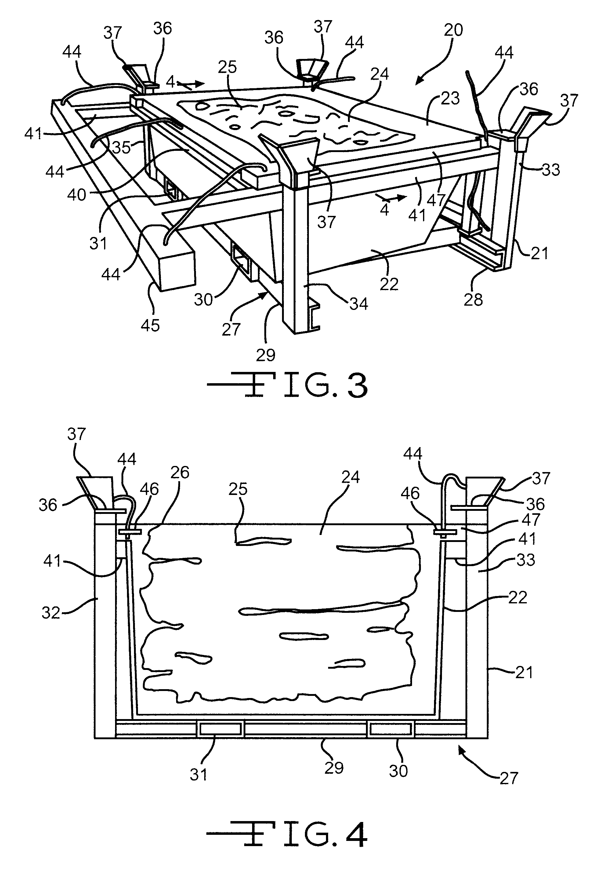
[0006]The apparatus may include a form having a rigid support frame and a resilient insert which forms a cavity in which the block is cast. The surfaces of the insert which define the cavity are textured to form the surfaced of blocks cast in the cavity, and may include portions which project some distance into the cavity. The frame provides support for the resilient insert when concrete is poured into the insert cavity and while the concrete cures. When the form is turned upside down, a sufficient relief angle is provided between the frame and the insert to allow the insert to fall freely from the frame. Edges or corners of the insert are loosely secured to the frame, for example, with cables, chains, bolts or rods, so that when the frame is inverted, the insert will fall only a short distance from the frame. After a concrete block cast in the mold insert cavity has cured, the support frame is inverted so that the mold insert will fall a short distance from the frame. The weight of the block causes the resilient insert to distort and bend away from sides of the block, allowing the block to fall freely from the insert.

Problems solved by technology

Because of the irregular surfaces, these blocks are not easily released from the form cavity in which they are cast.
The manual labor required to release or move the form sides from the each block so that it can be removed from the form adds to the cost for manufacturing the blocks.
It has been particularly difficult to manufacture large concrete blocks having highly irregular surfaces which have the appearance of natural stone.

Method used


Image

  • Method and apparatus for forming concrete blocks
  • Method and apparatus for forming concrete blocks
  • Method and apparatus for forming concrete blocks

Examples


Embodiment Construction

[0020]In the following description of the invention, certain terminology will be used for the purpose of reference only, and are not intended to be limiting. Terms such as “upper” and “lower” refer to directions in the drawings to which reference is made. Terms such as “top”, “bottom”, “horizontal”, and “vertical” describe the orientation of portions of the component within a consistent but arbitrary frame of reference which is made clear by reference to the text and the associated drawings describing the component under discussion. Such terminology will include the words specifically mentioned above, derivatives thereof, and words of similar import.

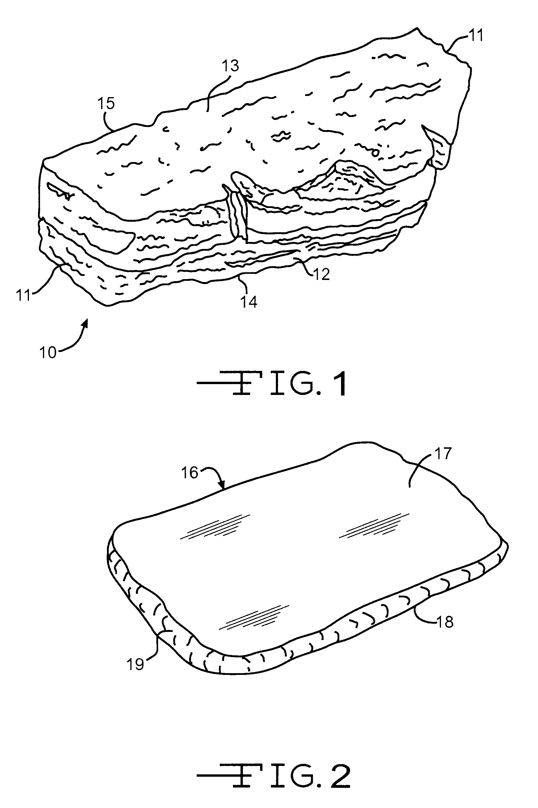
[0021]FIG. 1 of the drawings illustrates an exemplary cast concrete retaining wall block 10 which is formed to simulate a highly weathered sandstone block or other types of highly textured rock. The sides 11, front 12, top 13 and bottom 14 surfaces of the block may have numerous irregular undercuts which simulate fissures and erosion pat...


PUM

PropertyMeasurementUnit
weightaaaaaaaaaa
weightaaaaaaaaaa
shapeaaaaaaaaaa

Abstract

A method and apparatus for forming a concrete block in form having a resilient insert forming a cavity in which the block is cast and a rigid support for the resilient insert. After the block has cured, the form is inverted. One or more areas of the insert are tethered to the support so that at least a portion of the insert can fall a short distance from the support. The weight of the cast block sufficiently deforms the insert to allow the block to fall free from the insert. When the form is again inverted to its upright position, the insert falls back into the support and returns to its original shape.

Description

CROSS-REFERENCE TO RELATED APPLICATIONS[0001]Not Applicable.STATEMENT REGARDING FEDERALLY SPONSORED RESEARCH OR DEVELOPMENT[0002]Not Applicable.TECHNICAL FIELD[0003]The invention relates to a method and apparatus for casting concrete blocks.BACKGROUND OF THE INVENTION[0004]Concrete blocks may be formed with textured sides which may have undercuts. Because of the irregular surfaces, these blocks are not easily released from the form cavity in which they are cast. The shapes of the form cavity walls are such that the cured concrete block is locked within the form, even if the form is inverted. One method for releasing blocks with irregular surfaces from the form cavity is to hinge the side walls of the cavity so that the form walls may be pivoted away from the cast block after the concrete has sufficiently cured. This allows the block to be lifted from the form. Another method is to provide form walls which can be manually disassembled and separated from the block after it has cured, ...

Claims


Application Information

Patent Timeline
Patent Type & Authority Patents(United States)
IPC IPC(8): B29C39/36
CPCB28B7/06B28B7/08B28B7/065
Inventor MANTHEI, JAMES A.MANTHEI, JEREMY L.
Owner ROSETTA HARDSCAPES
Learn More