Corrugated tube fitting with a ridge sealing device and method

a sealing device and corrugated tube technology, applied in the direction of hose connection, pipe connection arrangement, pipe-joint, etc., can solve the problems of less robust and unpredictable seals, negative impact on long-term durability, etc., to avoid durability and reliability problems, less robust and unpredictable, the effect of more robust seals

Active Publication Date: 2009-11-24
TITEFLEX
View PDF28 Cites 24 Cited by
  • Summary
  • Abstract
  • Description
  • Claims
  • Application Information

AI Technical Summary

Benefits of technology

[0010]The metal-to-metal seal preferably is formed without the use of gaskets or elastomers sometimes used in conventional fittings, where the presence of gaskets or elastomers, which may be prone to deterioration, can negatively impact long-term durability by making the seal less robust and unpredictable due to polymer chain degradation and polymer material leeching (hardening and cross-sectional shrinkage). Moreover, use of a ridge geometry in the metal-to-metal seal according to the present invention can provide significant advantages over conventional sealing techniques, which utilize generally flat or smooth sealing surfaces. For example, the sealing ridges tend to form a more robust seal by presenting a feature, i.e., the ridge, which creates concentrated annular stress and / or deformation ring(s) with at least some overall tolerance for misalignment or component manufacturing variances, thereby avoiding durability and reliability problems that plague conventional fittings.
[0011]According to the present invention, the ridges used to form the metal-to-metal seal are spaced apart in a manner to maximize sealing pressure, and produce stress concentrations and / or localized deformations, in order to create at least one of: a seal at lower torques, a seal on stiffer tubing, or a seal on tubing that may have at least one minor defect such as a dent or weld. The sealing device is particularly useful for sealing an end corrugation of tubing in a fitting used in gas and liquid piping systems.

Problems solved by technology

The metal-to-metal seal preferably is formed without the use of gaskets or elastomers sometimes used in conventional fittings, where the presence of gaskets or elastomers, which may be prone to deterioration, can negatively impact long-term durability by making the seal less robust and unpredictable due to polymer chain degradation and polymer material leeching (hardening and cross-sectional shrinkage).

Method used


Image

  • Corrugated tube fitting with a ridge sealing device and method
  • Corrugated tube fitting with a ridge sealing device and method
  • Corrugated tube fitting with a ridge sealing device and method

Examples


Embodiment Construction

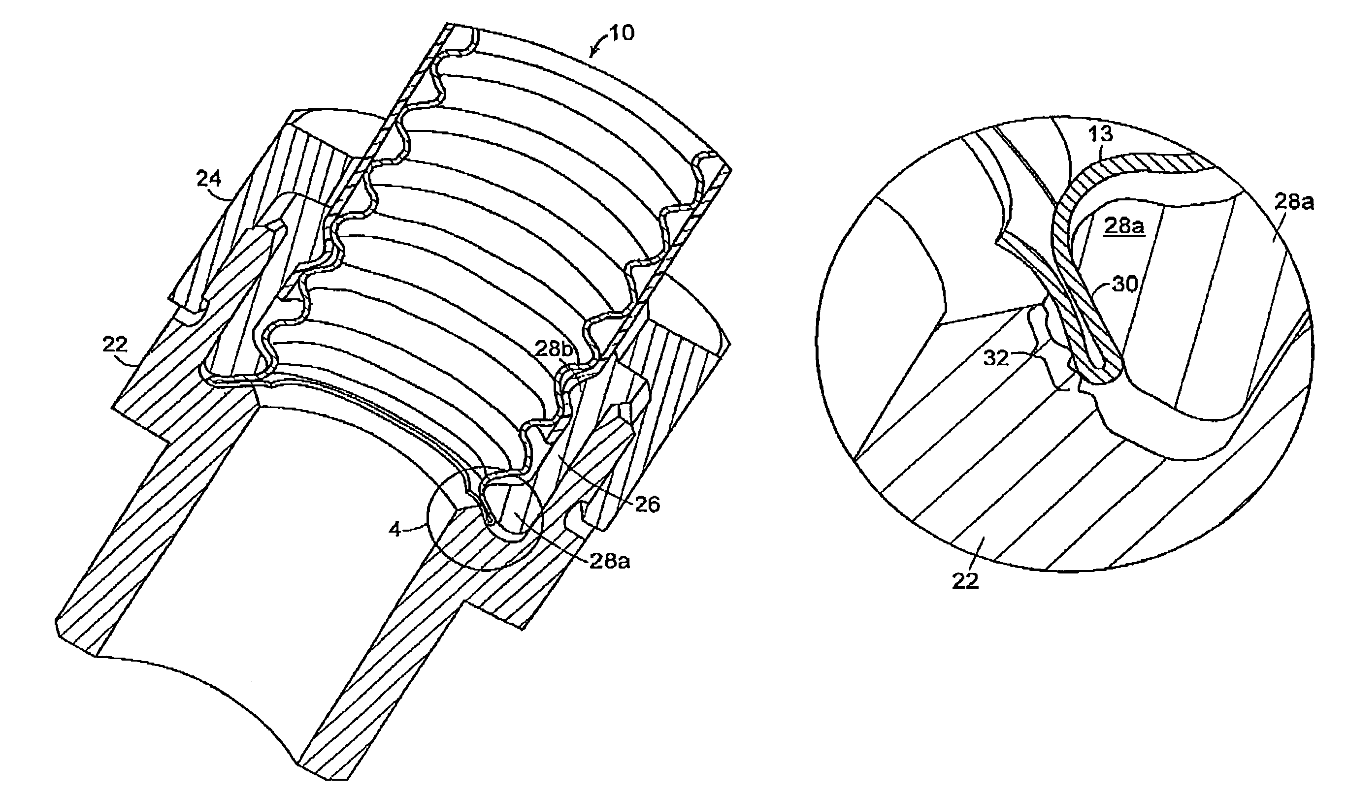
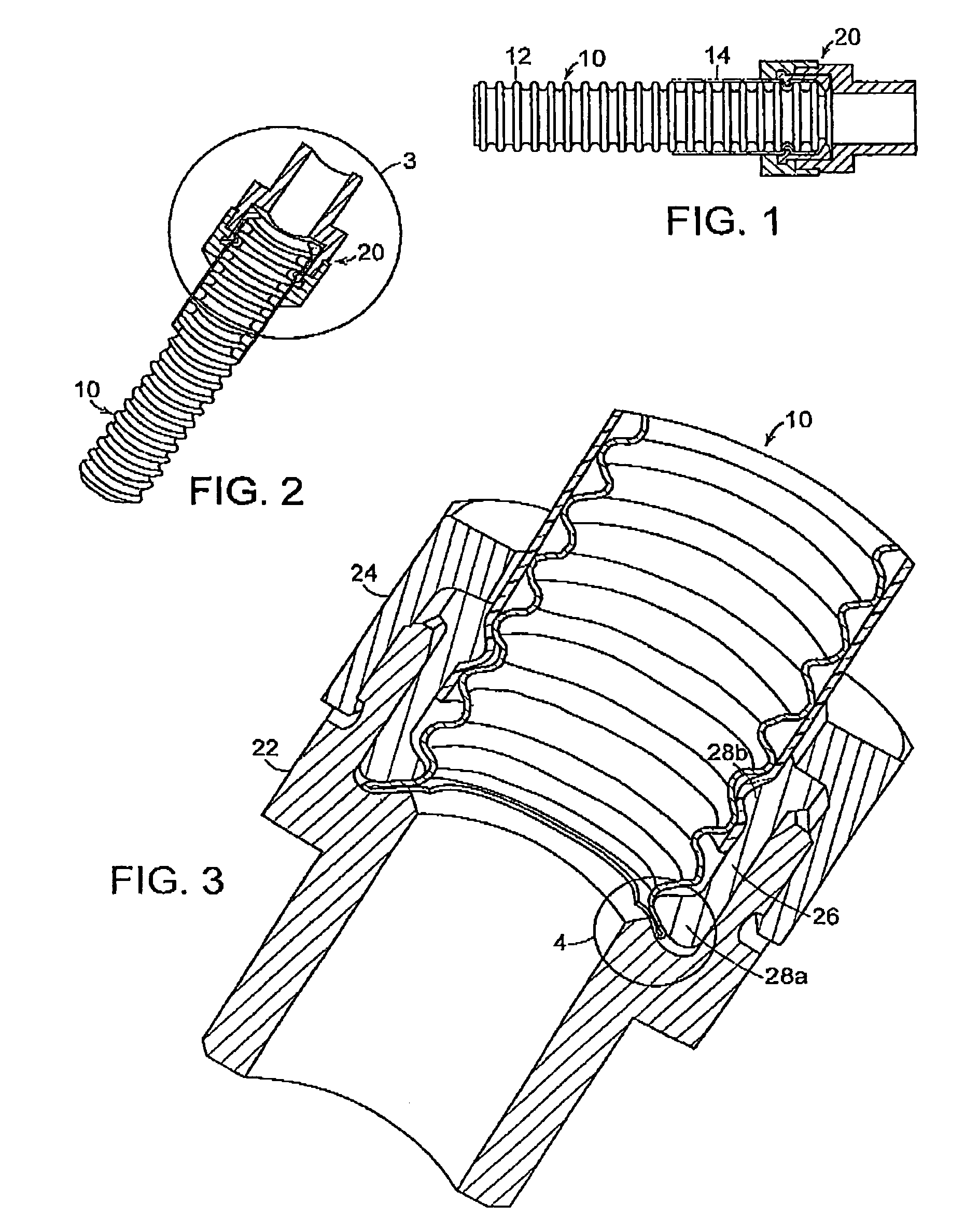
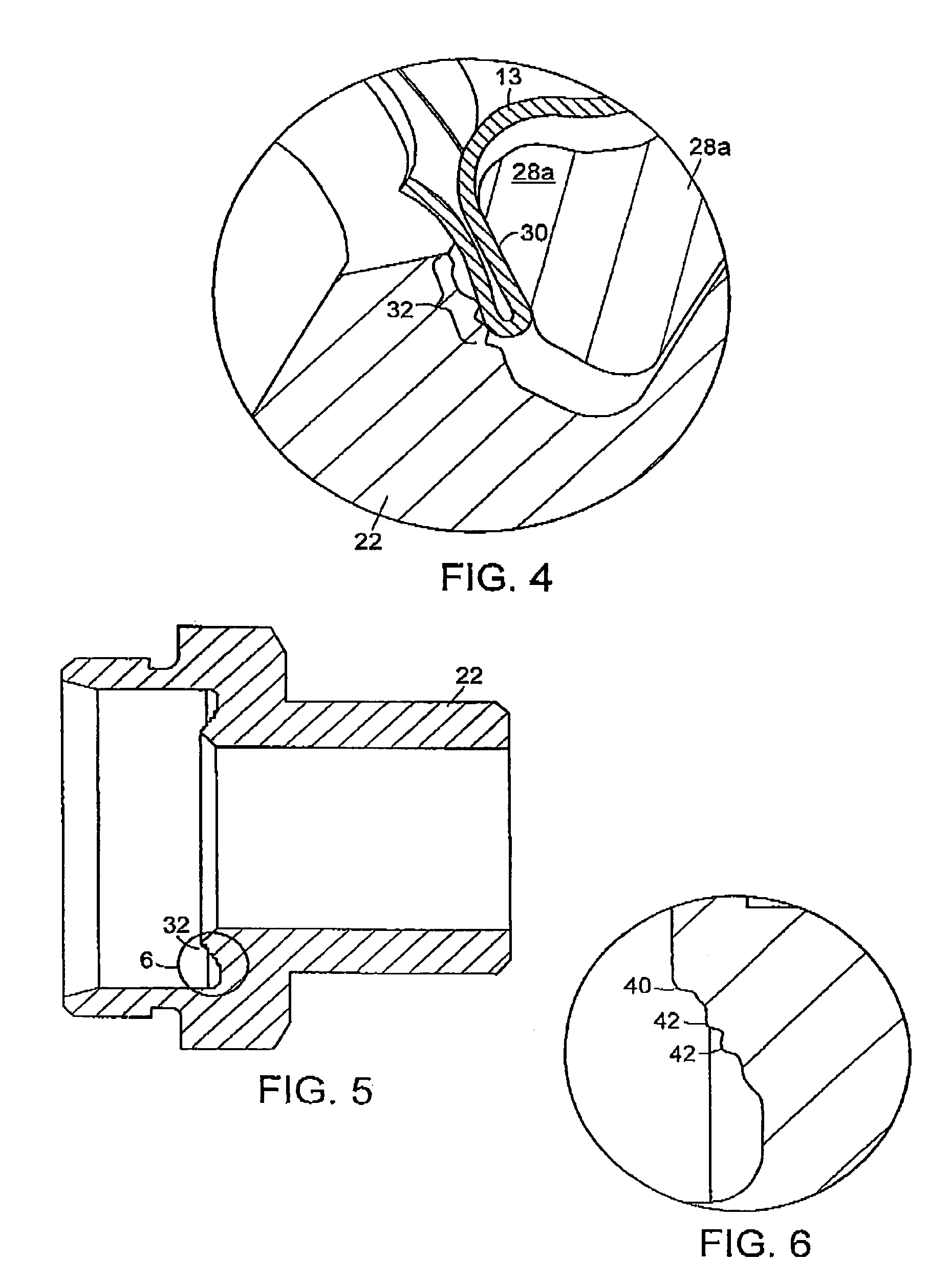
[0030]A fitting according to the present invention incorporates a sealing device having a ridge geometry, preferably a plurality of sealing ridges provided on at least one sealing surface. The fitting can be connected to a length of tubing, such as corrugated stainless steel tubing (CSST), commonly used in gas and liquid piping systems. Alternatively, the fitting can be connected to another fitting using the ridge geometry.

[0031]In various embodiments as described herein, the fitting incorporating the sealing device of the present invention forms a metal-to-metal seal with a length of tubing, where the seal preferably is formed by collapsing or compressing at least one corrugation of the length of tubing. For example, the end corrugation of the tubing can be sealed to the fitting, thereby forming a metal-to-metal seal. Use of a ridge geometry in the metal-to-metal seal according to the present invention can improve reliability and durability as compared to conventional sealing techn...


PUM


Abstract

A sealing device and method for sealing a length of tubing with a fitting is provided, where the sealing device includes at least one sealing surface formed with a plurality of ridges. The ridges include at least one end ridge and at least one internal ridge which are spaced apart by a predetermined distance, and formed with a desired geometry such as U-shaped, V-shaped, or various other shapes and with different sealing faces such as curved or flat. The ridges are spaced apart in a manner to maximize sealing pressure, and produce stress concentrations and localized deformations, in order to create a seal at lower torques or on stiffer tubing or tubing with at least one minor defect such as a dent or weld. The sealing device is particularly useful for sealing an end corrugation of tubing in a fitting used in gas and liquid piping systems.

Description

FIELD OF INVENTION[0001]The present invention relates to gas and liquid piping systems, and more particularly to a device and method for forming a seal between a length of corrugated tubing and a fitting, the fitting incorporating a sealing device with a ridge geometry.BACKGROUND OF THE INVENTION[0002]Gas and liquid piping systems which utilize corrugated stainless steel tubing (“CSST”) and fittings are known. Such piping systems can be designed for use in combination with elevated gas pressures of up to about 0.03 megapascals (MPa) or more, and provide advantages over traditional rigid black iron piping systems in terms of ease and speed of installation, elimination of onsite measuring, and reduction in the need for certain fittings such as elbows, tees, and couplings. Undesirably, some fittings conventionally used with CSST systems include fiber sealing gaskets which can deteriorate over time, or pre-flared tubing ends, which suffer from reliability problems.[0003]A suitable self-...

Claims


Application Information

Patent Timeline
Patent Type & Authority Patents(United States)
IPC IPC(8): F16L25/00
CPCF16L19/041F16L25/0036Y10S285/903
Inventor DUQUETTE, SCOTTKELLAR, FRANZ
Owner TITEFLEX
Why Eureka
Try Eureka