Sealing device with ridges for corrugated stainless steel tubing

a technology of stainless steel tubing and sealing device, which is applied in the direction of hose connections, pipe joints, pipe elements, etc., can solve the problems of less robust seals, unpredictable, and negative impact on long-term durability, and achieve reliable seals.

Active Publication Date: 2009-10-27
TITEFLEX
View PDF28 Cites 29 Cited by
  • Summary
  • Abstract
  • Description
  • Claims
  • Application Information

AI Technical Summary

Benefits of technology

[0011]The metal-to-metal seal preferably is formed without the use of gaskets or elastomers sometimes used in conventional fittings, where the presence of gaskets or elastomers, which may be prone to deterioration, can negatively impact long-term durability by making the seal less robust and unpredictable due to polymer chain degradation and polymer material leeching (hardening and cross-sectional shrinkage). Moreover, use of a plurality of ridges forming a ridge-like geometry in the metal-to-metal seal according to the present invention can provide significant advantages over conventional sealing techniques, which utilize generally flat or smooth sealing surfaces. For example, the sealing ridges tend to form a more robust seal by presenting a feature, i.e., the ridge, which creates concentrated annular stress and / or deformation ring(s) with at least some overall tolerance for misalignment or component manufacturing variances, thereby avoiding durability and reliability problems that plague conventional fittings.
[0012]According to the present invention, the ridges used to form the metal-to-metal seal are spaced apart in a manner to maximize sealing pressure, and produce stress concentrations and / or localized deformations, in order to create at least one of: a seal at lower torques, a seal on stiffer tubing, or a seal on tubing that may have at least one minor defect such as a dent or weld. The sealing device is particularly useful for sealing an end corrugation of tubing in a fitting used in gas and liquid piping systems.
[0015]According to second and third preferred embodiments of the present invention, a collapsed outer diameter of the at least one corrugation of tubing is controlled to produce a substantially circular profile or shape. In the second embodiment, an inner diameter of the main body is sized to maintain a generally circular shape of the collapsed end corrugation, where the end corrugation can contact an inner wall of the main body during sealing. In the third embodiment, an inner diameter of the bushing is sized to maintain a generally circular shape of the collapsed end corrugation, where the end corrugation can contact an inner wall of the bushing during sealing. In the second and third embodiments, the inner wall of the main body or bushing, respectively, restricts outward movement of the end corrugation, such that an inner diameter of the main body or bushing and the end corrugation essentially form an interference fit. As a result, the collapsed end corrugation has a generally circular shape, and remains substantially concentric with the remainder of the length of tubing.
[0016]Control of the outer diameter of the one or more collapsed corrugations is achieved by allowing the tubing to contact an inner wall of the main body of the fitting and / or the bushing, as provided in the second and third embodiments. By forming the one or more collapsed corrugations with a circular profile or shape, suitable sealing contact is made between the first and second sealing surfaces and the collapsed corrugations, thus providing a reliable seal.

Problems solved by technology

The metal-to-metal seal preferably is formed without the use of gaskets or elastomers sometimes used in conventional fittings, where the presence of gaskets or elastomers, which may be prone to deterioration, can negatively impact long-term durability by making the seal less robust and unpredictable due to polymer chain degradation and polymer material leeching (hardening and cross-sectional shrinkage).

Method used


Image

  • Sealing device with ridges for corrugated stainless steel tubing
  • Sealing device with ridges for corrugated stainless steel tubing
  • Sealing device with ridges for corrugated stainless steel tubing

Examples


first embodiment

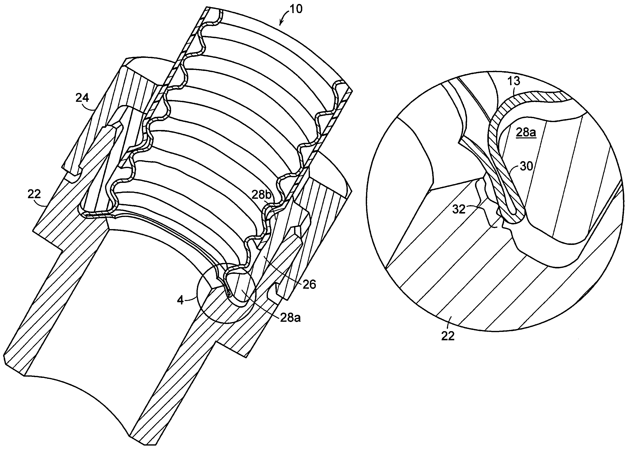
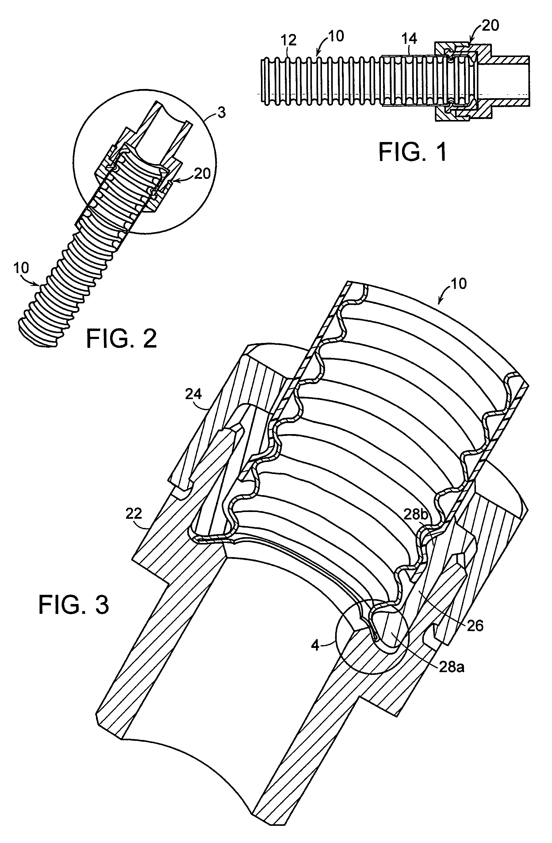
[0054]Referring again to FIGS. 13A-13B, the components of the fitting 120 are generally the same as those depicted in FIGS. 3 and 4. The fitting 120 includes a main body (or adapter) 122 having a bore for receiving the tubing 110. The fitting 120 also includes a nut 124 and a split bushing 126 received in the main body 122 of the fitting. As shown in FIG. 13A, the split bushing 126 includes at least two spaced apart internal ribs 128a and 128b for engaging circumferential grooves of the tubing 110. The internal ribs 128a and 128b can engage and align the tubing 110 and / or jacket 114 within the split bushing 126, thereby centering the tubing 110 within the fitting 120 such that at least one corrugation of the tubing 110 is received between sealing surfaces of the main body 122 and the split bushing. The internal ribs 128a and 128b also provide strain relief where the outer diameter of the corrugated tubing engages the split bushing 126. Further, the split bushing 126 can include one ...

third embodiment

[0058]Referring to FIGS. 15A-15B, the components of the fitting 210 include a main body 20 (or adapter) 222 having a bore for receiving a length of tubing 210. The fitting 220 also includes a nut 224 and a split bushing 226 received in the main body 222 of the fitting. In FIGS. 15A-15B, the fitting 220 is formed with internal ribs 228a and 228b that can engage and align the tubing 210 and / or jacket 214 within the split bushing 226, such that at least one end corrugation of the tubing 210 is received between sealing surfaces of 25 the main body 222 and the split bushing 226. The internal ribs 228a and 228b also provide strain relief where the outer diameter of the corrugated tubing engages the split bushing 226. Further, the split bushing 226 includes one or more additional contact points 227 with the tubing 210 and / or jacket 214 for aligning the tubing within the fitting and relieving strain. In other words, the split bushing 226 includes various contact points or regions for contac...


PUM


Abstract

A sealing device and method for sealing a length of tubing with a fitting, where the sealing device includes at least one sealing surface formed with a plurality of ridges. The sealing device is particularly useful for sealing at least an end corrugation of tubing in a fitting used in gas and liquid piping systems. The fitting is sized to maintain a generally circular shape of the end corrugation after the corrugation is collapsed between the ridged sealing surface and another sealing surface. In particular, an inner diameter of one or more components of the fitting can be sized such that the corrugated tubing will have a circular profile to provide an optimal seal.

Description

CROSS-REFERENCE TO RELATED APPLICATION[0001]This application is a continuation-in-part of copending application Ser. No. 11 / 440,740 filed on May 24, 2006, the disclosure of which is expressly incorporated herein by reference in its entirety.FIELD OF THE INVENTION[0002]The present invention relates to gas and liquid piping systems, and more particularly to a device and method for forming a seal between a length of corrugated tubing and a fitting, the fitting incorporating a sealing device with ridges, and capable of controlling-a sealing profile.BACKGROUND OF THE INVENTION[0003]Gas and liquid piping systems which utilize corrugated stainless steel tubing (“CSST”) and fittings are known. Such piping systems can be designed for use in combination with elevated gas pressures of up to about 0.03 megapascals (MPa) or more, and provide advantages over traditional rigid black iron piping systems in terms of ease and speed of installation, elimination of onsite measuring, and reduction in th...

Claims


Application Information

Patent Timeline
Patent Type & Authority Patents(United States)
IPC IPC(8): F16L25/00
CPCF16L19/041F16L25/0036Y10S285/903
Inventor DUQUETTE, SCOTTKELLAR, FRANZ
Owner TITEFLEX
Why Eureka
Try Eureka