Meal tray with advertising display

a technology of food trays and display cases, which is applied in the direction of identification means, instruments, chairs, etc., can solve the problems of short time available for changing the display between flights, theft or vandalism, and display protection, and it is undesirable to employ a mounting structure which is too complex

Active Publication Date: 2009-11-24
BE AEROSPACE INCORPORATED
View PDF28 Cites 49 Cited by
  • Summary
  • Abstract
  • Description
  • Claims
  • Application Information

AI Technical Summary

Benefits of technology

[0038]FIGS. 3 and 4 illustrate the insert 40, which has opposed forward and aft faces 48 and 50, and top, bottom, left, and right edges designated 52A, 52B, 52C and 52D, respectively. Opposed side tabs 54A and 54B extend laterally from the left and right edges 52C and 52D, respectively, and a top tab 56 extends from the top edge 52A. A view opening 58 is formed through the insert 40, and a boss 60 surrounds the perimeter of the view opening 58. A transparent protective panel 62 is bonded to a shelf 64 formed in the boss 60, and a retaining panel 66 is bonded to the outer edge 68 of the boss 60. An access slot 70 may be provided in the retaining panel 66. As shown in FIG. 3, a sheet 72 containing an advertisement, graphics, or other information to be displayed can easily be inserted into or removed from the space between the retaining panel 66 and the protective panel 62.
[0044]The cover also includes fastener elements 134 on the forward-facing surface of the cover 130 that are complementary to the fastener elements 122 on the recess 120 in both position and type, so that for example, if the fastener elements 122 are loop-type fasteners, then the fastener elements 134 are mating hook-type elements. The fastener elements 122 and 134 further secure the cover 130 to the meal tray 100, prevent gaps between the cover 130 and the meal tray 100, and provide an attachment that is sufficiently robust to retard tampering or removal except when removal is desired.
[0047]As is shown in FIG. 12, a suction cup 184 may be used to detach the cover 180 from the recess 170 without the need to extend a tool behind the cover 180 to pull the cover loose. This will prevent damage to the edges of the cover 180 and avoid the use of fingernails or other implements.

Problems solved by technology

These displays are subject to theft or vandalism and must be protected.
However, the time available for changing the displays between flights is short, and therefore it is undesirable to employ a mounting structure which is too complex.

Method used


Image

  • Meal tray with advertising display
  • Meal tray with advertising display
  • Meal tray with advertising display

Examples


Embodiment Construction

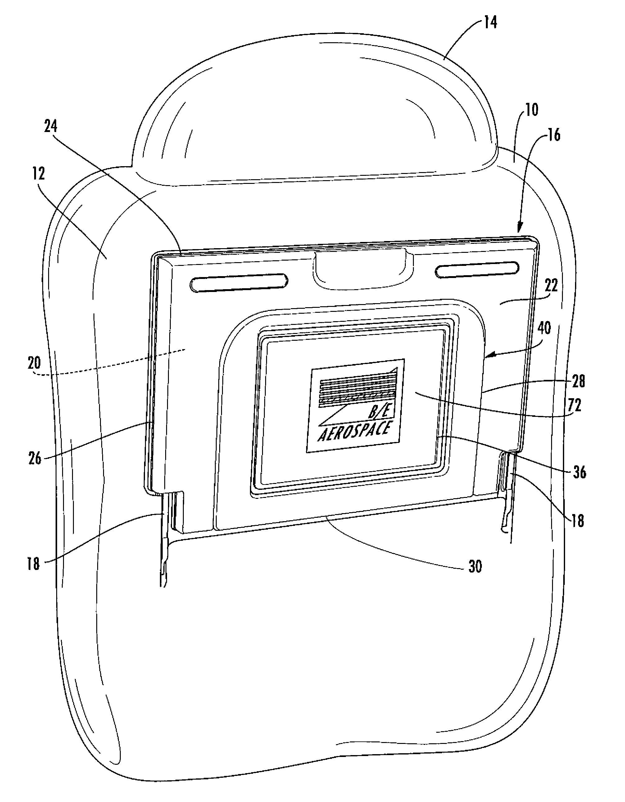
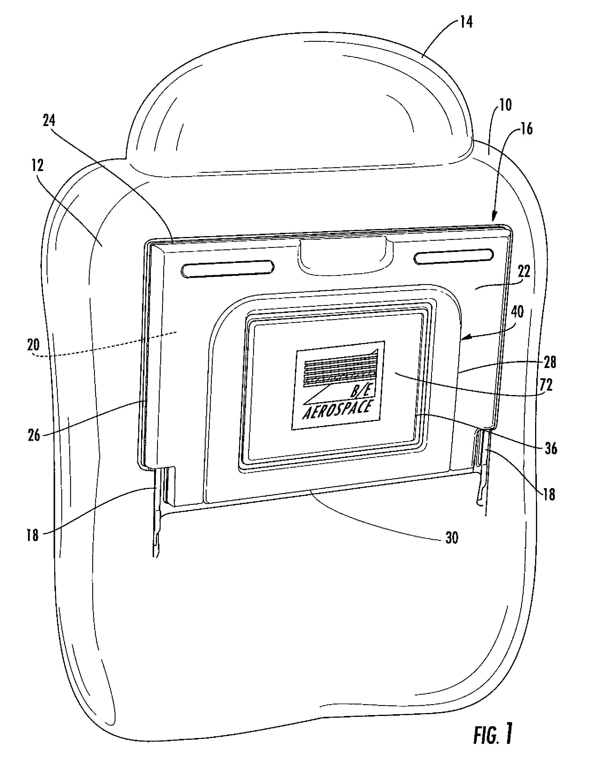
[0034]Referring to the drawings wherein identical reference numerals denote the same elements throughout the various views, an aircraft passenger seat back is illustrated in FIG. 1 and shown generally at reference numeral 10. It will be understood that the seat back 10 is part of a seat including a seat bottom and other conventional components not illustrated here. The present invention is equally applicable for use with other kinds of passenger seating, for example seating used in trains, buses or other vehicles. The seat back 10 includes a rear surface 12 and a headrest 14 positioned on an upper end thereof.

[0035]A meal tray 16 is carried on pivoting arms 18 or another suitable support structure, so that it can move in a conventional manner between a stowed position against the rear surface 12 of the seat back 10, and a deployed position in which it forms a generally horizontal surface for eating or other tasks.

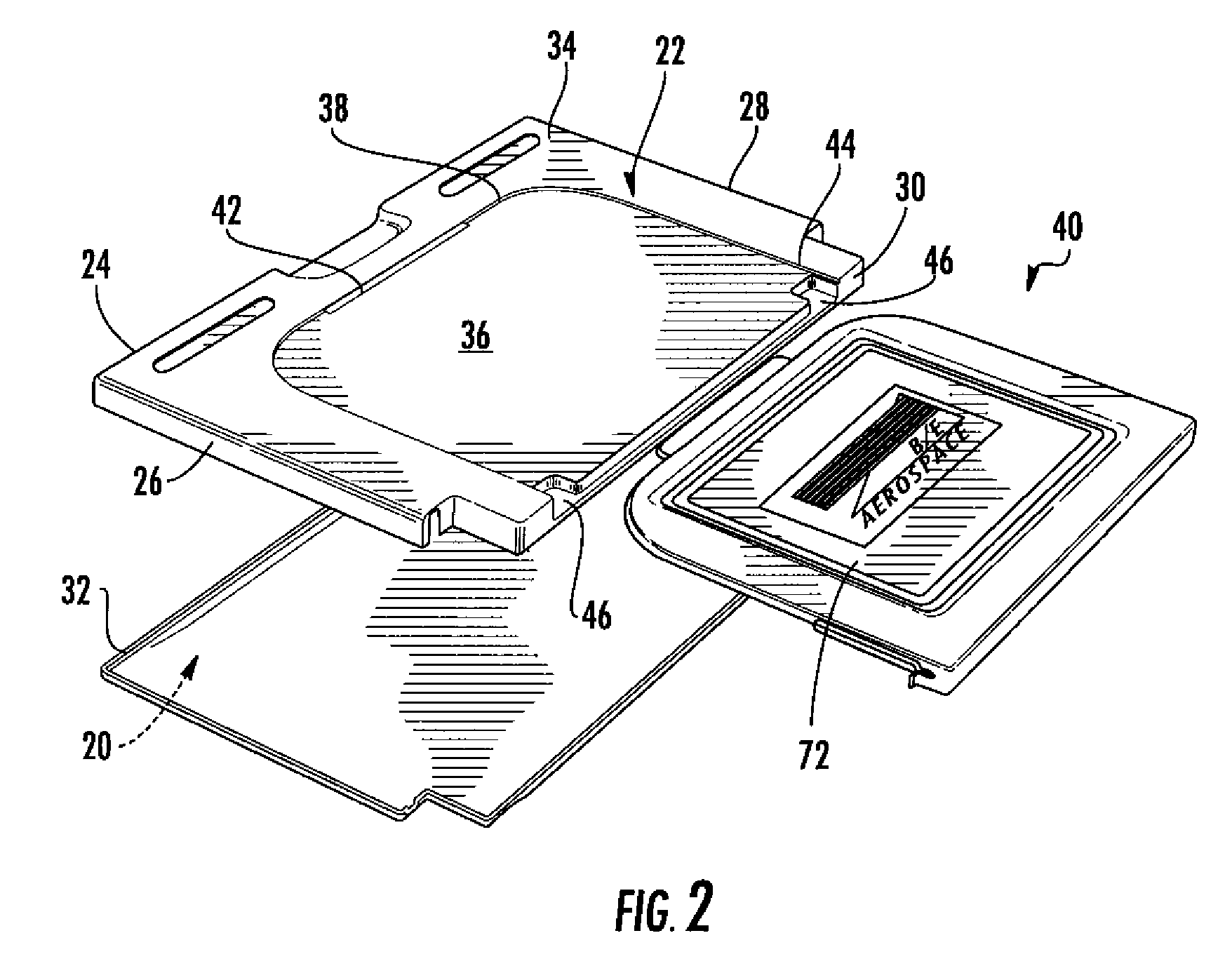
[0036]The meal tray 16 has a forward surface 20 and an aft surface 22 ...


PUM


Abstract

A meal tray for a passenger seat includes a removable insert. The insert carries a sheet of graphics or advertisements in a protected, viewable position when the meal tray is stowed. Tamper-resistant latches secure the insert to the meal tray.

Description

BACKGROUND OF THE INVENTION[0001]This invention relates generally to vehicle passenger seating and more particularly to a meal tray for a passenger seat unit.[0002]Commercial passenger aircraft seats often include seatback-mounted meal trays for use in consuming meals, holding work items, and the like. These trays typically fold between an upright, stowed position against the seat back of a seat forward of the user, and a lowered, deployed use position. It is known to adapt passenger seat meal trays to carry graphic displays with passenger information or advertisements.[0003]These displays are subject to theft or vandalism and must be protected. However, the time available for changing the displays between flights is short, and therefore it is undesirable to employ a mounting structure which is too complex. There is therefore a need for a display mounting device and system and is adapted particularly to the public transportation environment, for example, aviation, rail and bus trans...

Claims


Application Information

Patent Timeline
Patent Type & Authority Patents(United States)
IPC IPC(8): A47B83/02A47C7/62G09F3/00
CPCB60N3/004B64D11/0638B64D11/0015B64D11/00151
Inventor DICKINSON, MARTIN IAN
Owner BE AEROSPACE INCORPORATED
Why Eureka
Try Eureka